HTD timing pulley engineering and dimensional review

Engineering

Engineering pages are organised around the decisions that control an HTD pulley order: belt/profile identity, pitch family, tooth count, working width, shaft interface, construction, replacement measurement and order-specific inspection.

Decision guides

Move From Identification to a Controlled RFQ

Selection logic

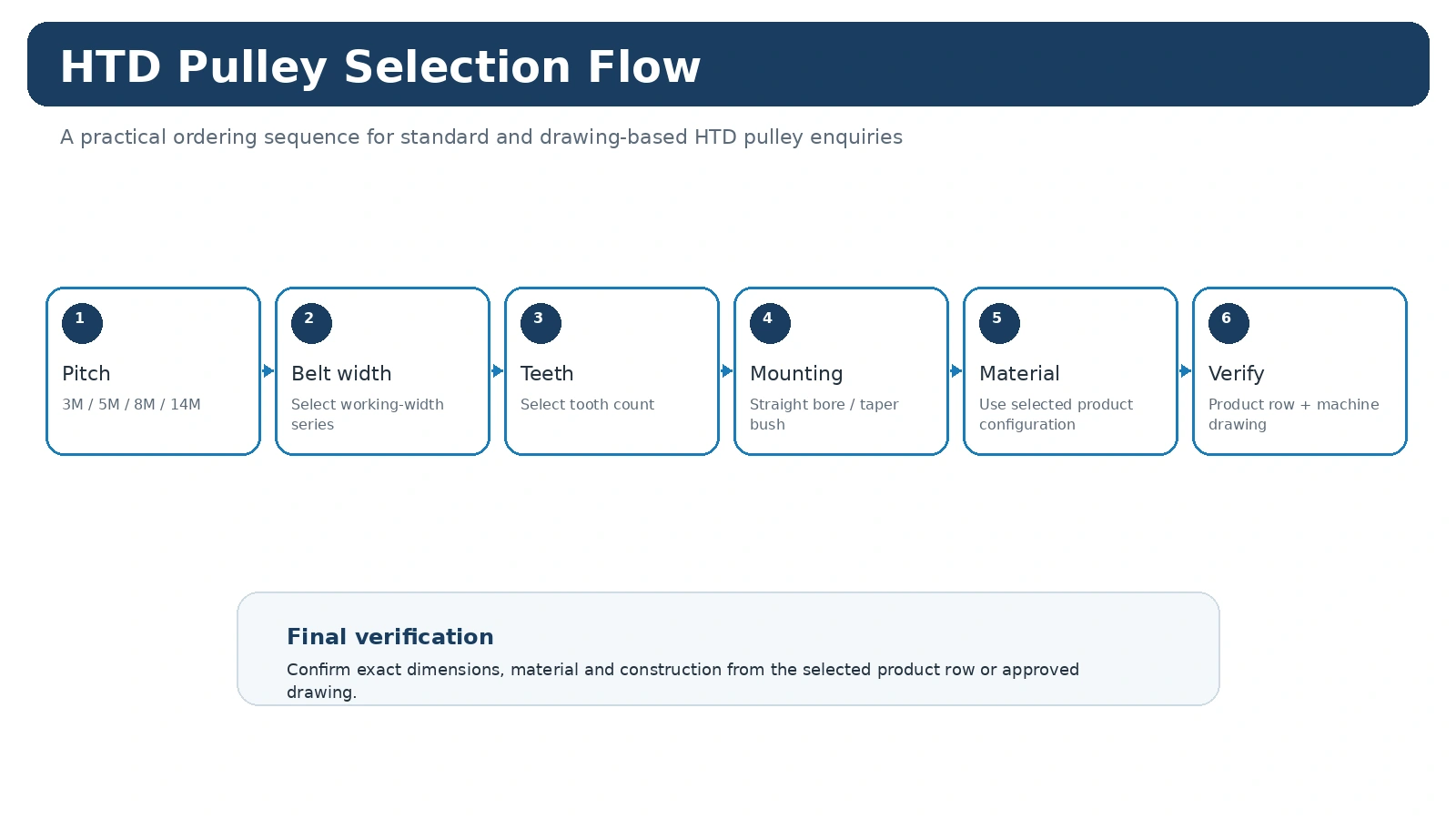
Measure → Classify → Compare → Verify → Quote

Replacement work should preserve the machine’s existing geometry before any comparison is made. New-drive work should begin from the required motion and load. In both cases, the last step is the same: verify the selected catalogue row or approved drawing before the product code is released to purchasing.

Where a required dimension, tolerance, material or compatibility point is missing, treat it as an RFQ question rather than filling the gap with a generic assumption.

HTD timing pulley selection flow
Technical drawings

Use Dimension Views at Full Readable Width

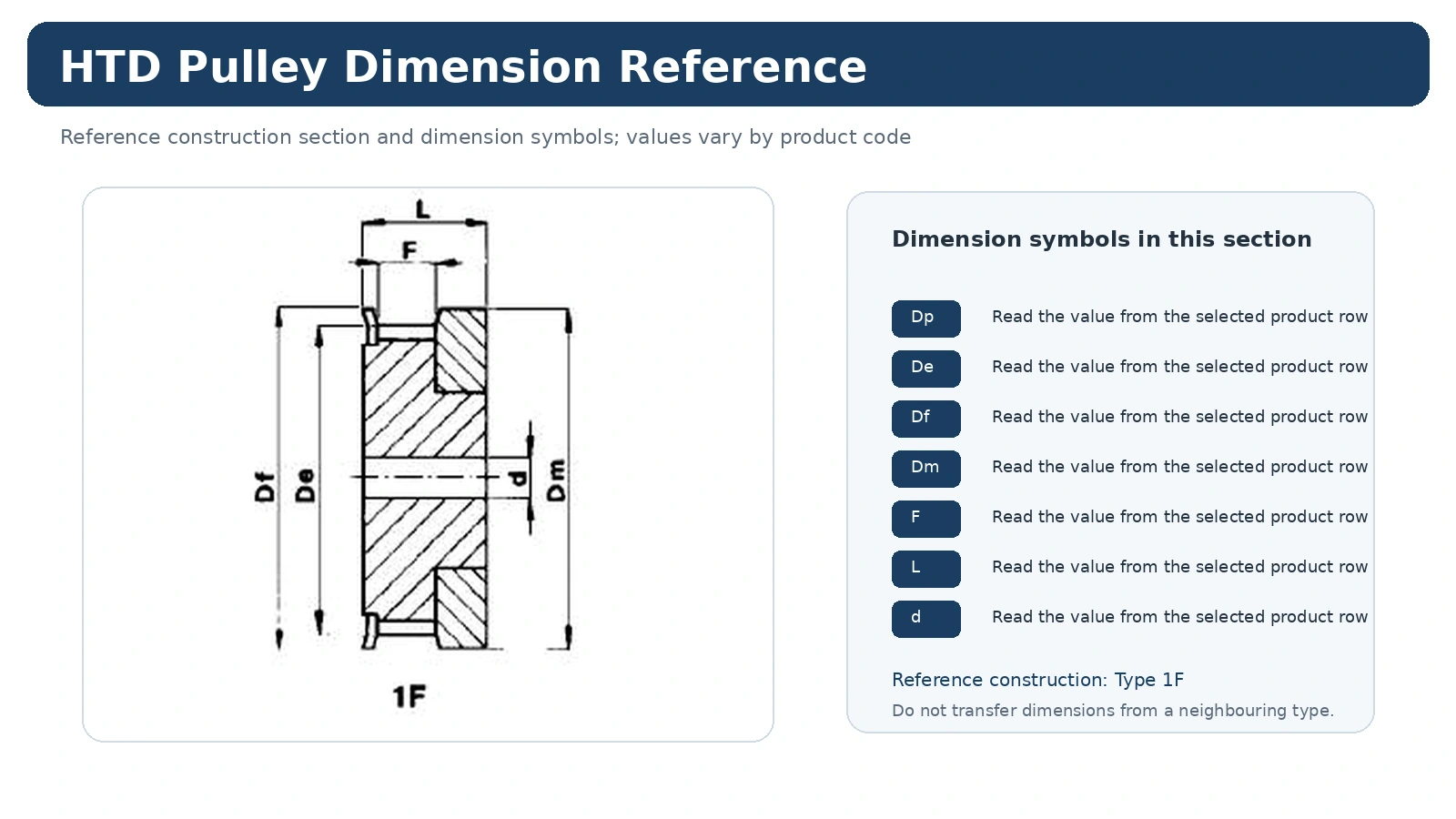
Dimension drawings on this site are displayed with contain behavior so labels and reference symbols are not cropped. The drawing defines the reference system; the model table supplies the values for a specific row.

HTD timing pulley dimension reference

Engineering Guides Use a Controlled Selection Sequence

The engineering section is organized around buyer decisions rather than isolated formulas. Start by identifying the belt family, then compare working width and tooth count inside that family. Once the belt-side geometry is fixed, review shaft connection, hub projection, flange arrangement and the installation envelope. This prevents a common failure in replacement sourcing: matching one visible diameter while overlooking the tooth system or the axial geometry that positions the belt.

Dimension drawings are used as nomenclature references, not as scale drawings. The product table controls the row-specific values. When a catalogue does not state a needed fit, tolerance, runout limit, material document or finish, that requirement belongs on the project RFQ or controlled drawing instead of being guessed from another series.

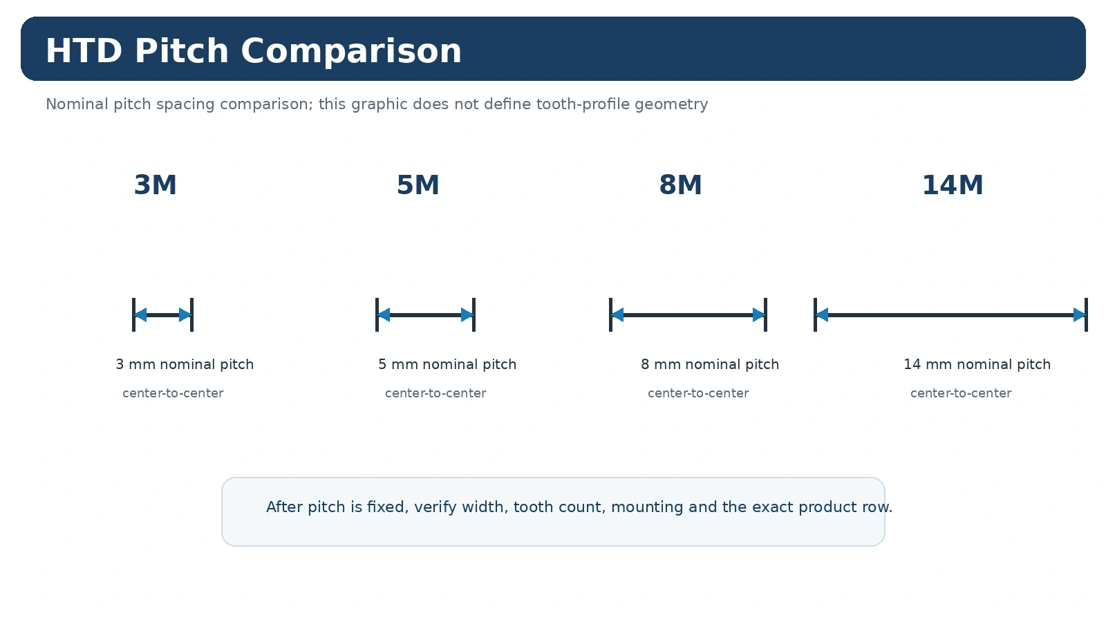
HTD 3M 5M 8M and 14M pitch comparison

Separate Belt Geometry From Shaft Geometry

HTD pitch and tooth count describe the synchronous relationship at the belt side. Bore, taper bush, keyway, hub length and flange construction solve a different problem: how the pulley installs on the machine and where the belt runs. A good RFQ keeps both sets of information together without treating one as proof of the other.

Use the pitch-comparison, measurement, bore-interface and straight-bore-versus-taper-bush guides as a sequence. If the existing drive is uncertain, send photographs and measurements rather than forcing the old part into a catalogue identity too early.

When a Drawing Becomes the Better Reference

A standard catalogue row works well when tooth family, width, tooth count and mounting already match the machine. Use a controlled drawing when bore, keyway, hub projection, flange location, material, finish, marking or inspection requirements differ from that row. The drawing should preserve the standard HTD identity and call out only the project-specific changes.

For replacement parts, a drawing is also useful when the original model is obsolete or when previous repairs have changed the shaft. In that case, record which dimensions came from the old part and which are new requirements so the approved revision becomes a clean baseline for the next replacement.