Timing Pulley Bore and Shaft Interface Guide: Capture bore, fit, keyway or bush, hub projection and axial belt-line references.
이 결정이 통제하는 것
Capture bore, fit, keyway or bush, hub projection and axial belt-line references. The decision should be documented with the belt designation, product code or drawing because a timing pulley is part of a drive system. A visual match does not prove tooth compatibility or shaft fit.
권장 워크플로
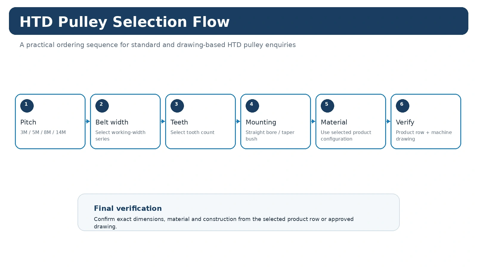
먼저 호환되는 벨트와 구동 장치 요구 사항을 확인합니다. 피치/프로파일, 톱니 수 및 작동 폭을 확인합니다. 그런 다음 샤프트 인터페이스, 허브 및 플랜지 윤곽, 재질 및 필요한 검사 사항을 점검합니다. 교체 시에는 기존 부품의 양쪽을 측정하고 안정적인 기계 기준점을 기준으로 벨트 라인을 기록합니다.
피해야 할 일반적인 오류
- 치아 구조를 무시하고 외경만 기준으로 선택하는 것.
- 동일한 공칭 피치를 가진 모든 곡선형 프로파일이 서로 호환된다고 가정합니다.
- 한쪽만 측정하고 허브 돌출부 또는 벨트 라인 오프셋을 누락한 경우.
- 견적 산출 후 보어 맞춤, 키홈, 부시 코드 또는 검사 요구 사항을 결정하십시오.
- 기계 및 벨트 설계 기준 없이 범용 벨트 장력 또는 허용 오차 값을 사용하는 것.
견적 요청서(RFQ) 작성 시 이 가이드를 활용하세요.
주요 변수를 확보했으면 엽니다. HTD 제품군관련 사항을 비교하십시오. 애플리케이션 컨텍스트또는 아래 양식을 통해 도면과 주문 세부 정보를 보내주세요.
Finish the Shaft Interface Only After the Pulley Family Is Fixed
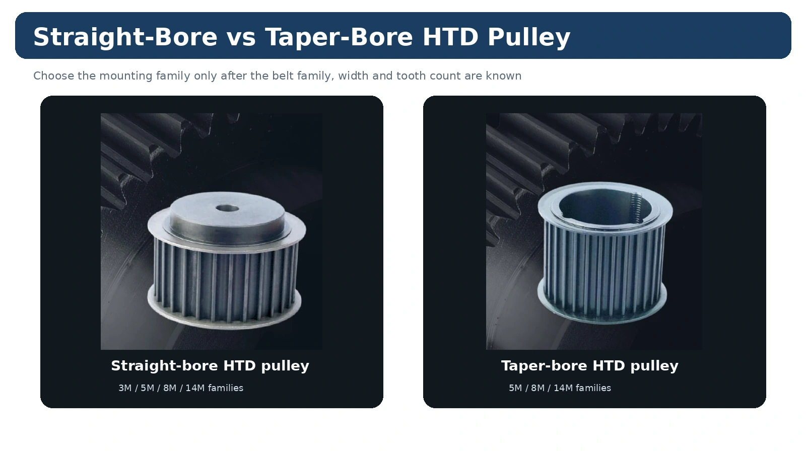
Confirm HTD family, width series and tooth count before finalizing bore or taper-bush details. This prevents a convenient shaft connection from steering the order toward the wrong belt-side geometry.
Record shoulders, spacers, keyway information and axial location from the actual machine. Any fit or tolerance not defined by the selected catalogue row should be controlled on the drawing.
Finish the Shaft Interface After the Belt-Side Geometry
First fix pitch family, width and tooth count. Then define shaft diameter, finished bore or supported taper bush, keyway or other locking detail where applicable, hub projection and belt centerline. These are installation variables, not tooth-profile variables.
기존 장비와 관련된 결정을 내릴 때는 측정값, 카탈로그 값 및 신규 프로젝트 요구 사항을 분리하여 관리해야 합니다. 이렇게 하면 현장 측정값이 명목 치수로 잘못 처리되거나 원하는 변경 사항이 표준 제품군 기능으로 오인되는 것을 방지할 수 있습니다.
도면과 표를 함께 사용하세요
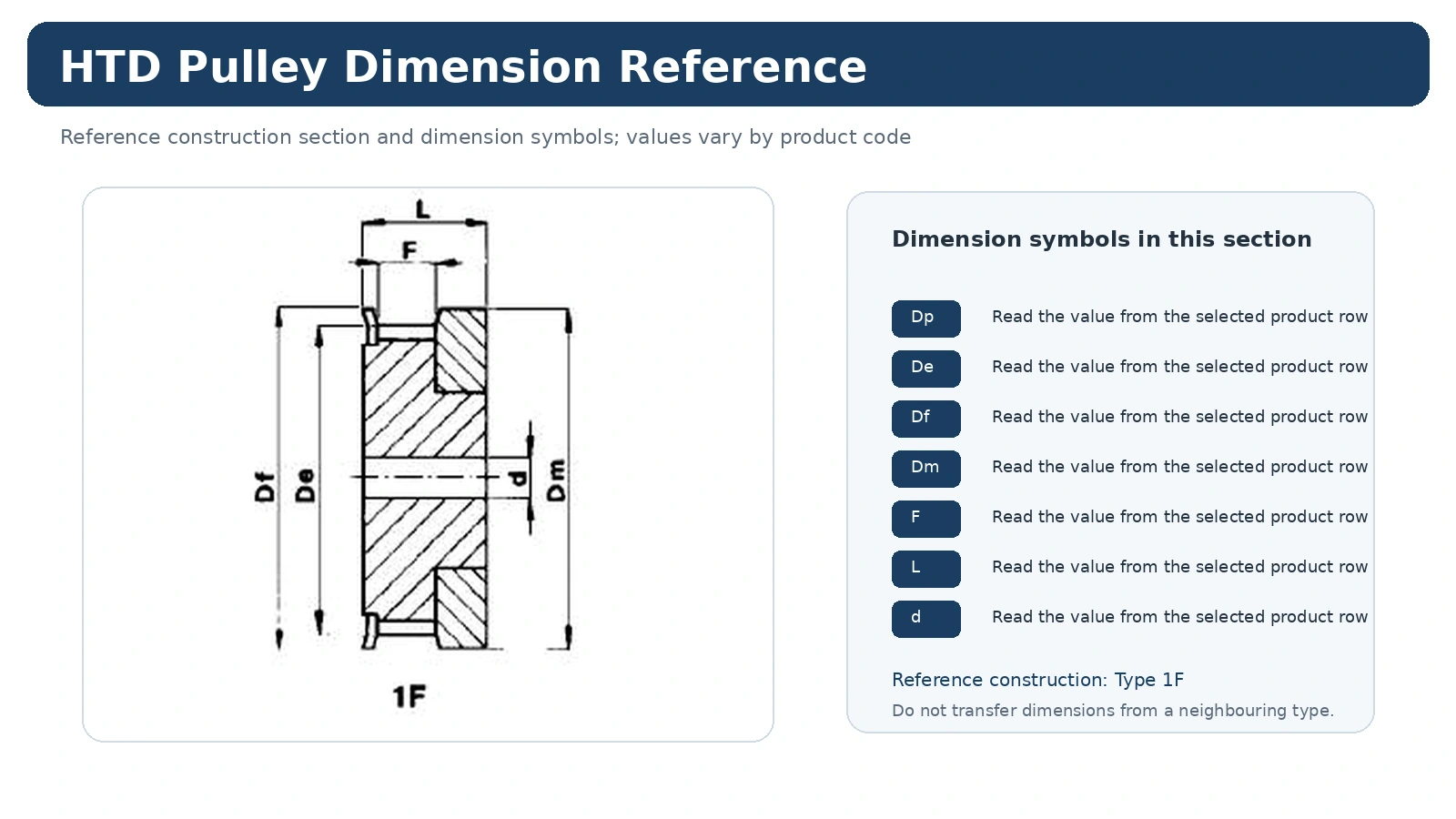
시공 도면은 기호와 그 관계를 설명합니다. 행별 표에는 선택한 모델의 실제 값이 나와 있습니다. 제품이 비슷해 보인다고 해서 그림을 확대하거나 다른 너비 또는 톱니 수의 치수를 그대로 사용하지 마십시오.
카탈로그에 필요한 맞춤, 런아웃, 공차, 마감 또는 문서에 대한 규정이 없는 경우, 해당 요구 사항을 프로젝트 도면이나 견적 요청서에 명시하고 주문 검토 과정에 포함시키십시오.
릴리스 체크리스트
벨트/프로파일 식별 정보, 작업 폭, 톱니 수, 장착 정의, 수량 및 도면 개정 정보를 동일한 기술 주문 라인에 기록하십시오. 새 구동 장치의 경우 기계 부하 사양을 추가하고, 교체 작업의 경우 선명한 사진과 치수를 첨부하십시오. 이렇게 하면 구매 담당자가 여러 개의 분리된 치수 대신 확인할 수 있는 구성 정보를 제공할 수 있습니다.
이 가이드가 대체하지 않는 내용
본 가이드는 제품 선정 및 측정 과정을 체계화하는 데 도움을 주는 자료이며, 정확한 제품 번호, 벨트 데이터 또는 프로젝트 도면을 대체하는 것은 아닙니다. 필요한 출력, 토크, 속도, 적합도, 공차 또는 사용 한계가 관련 카탈로그 표 또는 승인된 도면에 명시되어 있지 않은 경우, 설계 또는 견적 요청 시 입력 사항으로 활용하고 실제 구동 장치에서 확인하십시오.
해당 제한은 조달 과정에서 유용합니다. 왜냐하면 일반적인 엔지니어링 설명이 나중에 모든 HTD 풀리 구성에 대해 보장된 값인 것처럼 인용되는 것을 방지하기 때문입니다.
Apply the Bore And Shaft-Interface Review to a Real Machine
Collect shaft diameter, fit or tolerance when controlled, key/bush method, hub projection and axial datum. Use the catalogue or dimension drawing to name features consistently, then separate measured machine values from catalogue values. The working rule is simple: a bore number without the mounting method and hub geometry does not define the installed interface. If the old component is worn or modified, treat its measurements as field data rather than assuming they are the original nominal dimensions.
교체 작업 시에는 앞뒤 허브의 관계를 비교하고 벨트 라인을 결정하는 면을 기록해 두십시오. 새로운 설계의 경우, 제품 코드를 선택하기 전에 속도 관계, 중심 거리, 작동 조건 및 설치 범위를 기록해 두십시오. 이렇게 하면 나중에 구동 장치를 정비할 때 선택 내역을 추적할 수 있습니다.
도면을 사용하여 남은 빈 공간을 채우세요.
표준 제품 라인은 피치 계열, 톱니 수 및 여러 외형 치수를 정의할 수 있지만, 프로젝트별 축 맞춤, 주요 세부 사항, 허브 변경, 마감 처리 또는 검사 한계와 같은 세부 사항은 여전히 도면이 필요할 수 있습니다. 도면에 불필요한 참조 치수를 채우는 대신, 기계 기준점과 실제로 조립을 제어하는 치수를 표시하십시오.
카탈로그에 나와 있는 두 가지 구성이 가능해 보이는 경우, 아직 알려지지 않은 부분을 파악하고 해당 부분을 직접 측정하십시오. 이는 외경이 가장 가깝거나 가장 익숙한 사진을 기준으로 구성을 선택하는 것보다 더 신뢰할 수 있습니다.
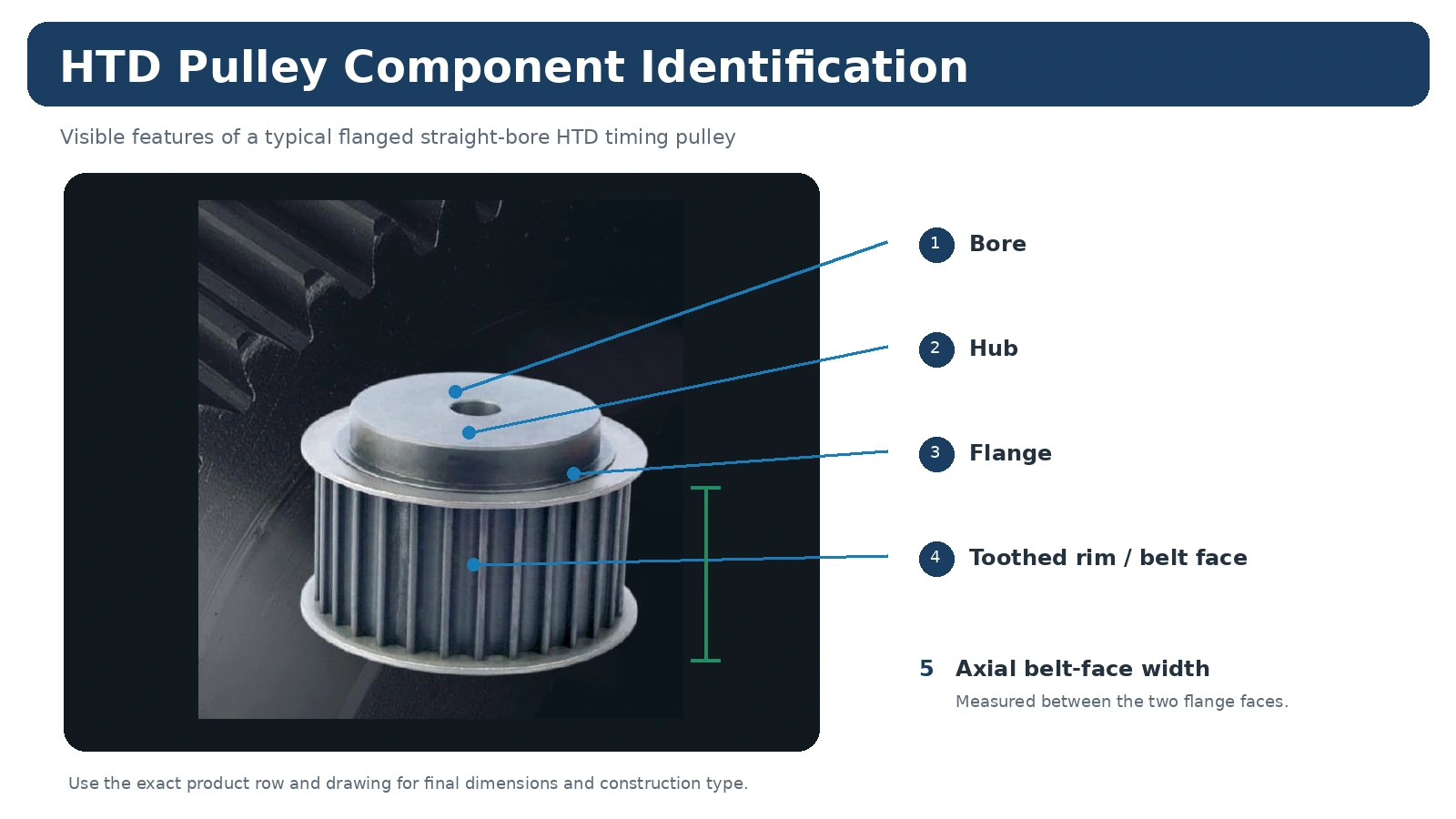
Release Data for Bore And Shaft-Interface Review
구매 라인에 HTD 제품군, 폭 시리즈, 톱니 수, 보어 또는 부싱 종류, 수량, 도면 개정판(사용되는 경우) 등 제품 식별 정보를 모두 기록해 두십시오. 주문별 재질, 마감, 검사 또는 문서 요구 사항은 별도로 추가하십시오. 이렇게 하면 승인된 구성을 이메일 기록에서 다시 확인하지 않고도 불러올 수 있으므로 나중에 교체 작업이 훨씬 쉬워집니다.
Release the Shaft Interface From a Drawing
Use a controlled drawing whenever bore fit, keyway geometry, hub projection or axial belt position affects assembly. Record the shaft diameter and tolerance, any key or locking element, available shoulder length, and the position of the belt centerline relative to the machine datum. If an existing pulley is being replaced, measure both sides before removal where possible. The catalogue row defines the pulley family; the released interface drawing should define the project-specific shaft connection.