
HTD 8M-50 Timing Pulley
8M curvilinear ہم وقت ساز وقت گھرنی، 8M-50 سیریز۔ کیٹلاگ ٹیبل یا منظور شدہ ڈرائنگ سے دانتوں کی گنتی، بیلٹ کی چوڑائی اور شافٹ انٹرفیس کا انتخاب کریں۔
HTD 8M-50 Timing Pulley Configuration Overview
8M-50 HTD ٹائمنگ پللی کیٹلاگ نام کے نظام میں 50 کے برائے نام بیلٹ-فیس حوالہ کے ساتھ ایک 8 ملی میٹر پچ مطابقت پذیر پللی فیملی ہے۔ یہ صفحہ سیریز کو ایک طے شدہ SKU کے بجائے ایک قابل ترتیب صنعتی جزو کے طور پر پیش کرتا ہے۔ دانتوں کی گنتی گھرنی کے قطر کو تبدیل کرتی ہے اور یہ حب، فلینج، مواد یا بڑھتے ہوئے تفصیلات کو بھی تبدیل کر سکتی ہے، لہذا آرڈر کو ایک مخصوص کیٹلاگ قطار یا منظور شدہ ڈرائنگ سے جوڑا جانا چاہیے۔
خریداری کے لیے، مکمل بیلٹ کے عہدہ کے ساتھ شروع کریں اور تصدیق کریں کہ میٹنگ بیلٹ وہی HTD 8M پروفائل استعمال کرتا ہے۔ ہر گھماؤ پٹی فیملی کے لیے اکیلے پچ ایک محفوظ تبادلہ اصول نہیں ہے۔ پروفائل کی تصدیق کے بعد، دانتوں کی گنتی اور کام کی چوڑائی کا انتخاب کریں، پھر شافٹ انٹرفیس، حب پروجیکشن، فلینج کے انتظام اور دستیاب مواد کا جائزہ لیں۔ یہ ترتیب دانتوں کے نظام یا بڑھتے ہوئے جیومیٹری کو نظر انداز کرتے ہوئے صرف بیرونی قطر کے ملاپ کی عام متبادل غلطی کو کم کرتی ہے۔
The straight-bore construction shown for this family is intended for positive synchronous power transmission. Typical enquiries come from machine tools, conveyors and higher-duty industrial motion. Actual suitability depends on speed, transmitted load, center distance, belt construction, alignment, environment and shaft support. Those duty inputs should be supplied for a new drive or when an existing machine has recurring belt-tracking or wear problems.
8M-50 کنسٹرکشن اور شافٹ انٹرفیس
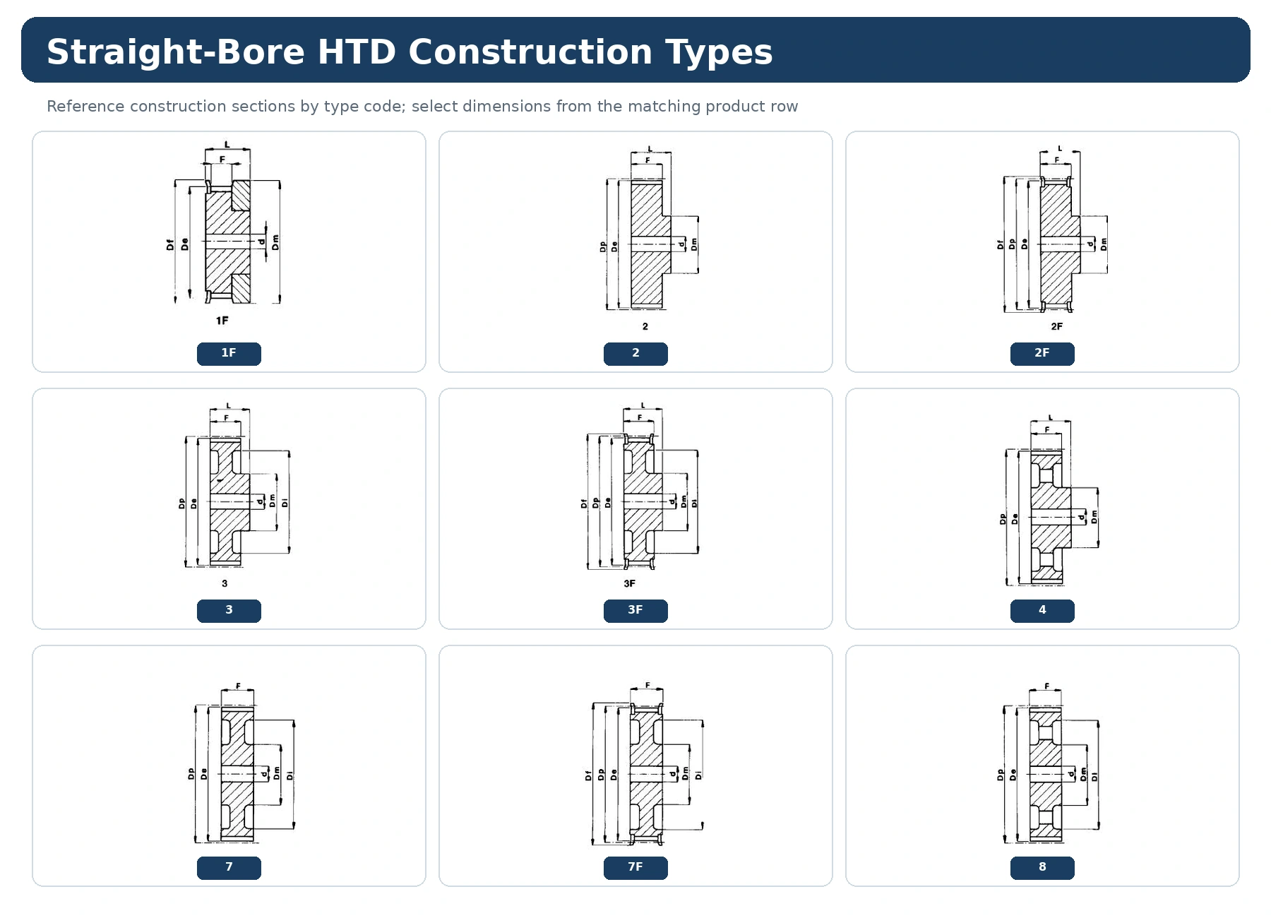
8M-50 belongs to the 8M HTD family and this page covers straight-bore construction. The catalogue table on this page spans 22–192 teeth. Construction codes visible in the table include 2F, 7F, 7, 8. Use the exact product code with the tooth count because the hub/flange arrangement can change inside one width series.
چوڑائی کوڈ 50 اس کیٹلاگ خاندان کی شناخت کرتا ہے؛ یہ میٹنگ بیلٹ مارکنگ اور ڈائمینشن ڈرائنگ کو چیک کرنے کا متبادل نہیں ہے۔ متبادل کام کے لیے، نصب شدہ بیلٹ لائن کو محفوظ رکھیں اور یہ فیصلہ کرنے سے پہلے کہ صحیح دانتوں والی قطار ایک مکینیکل متبادل ہے۔
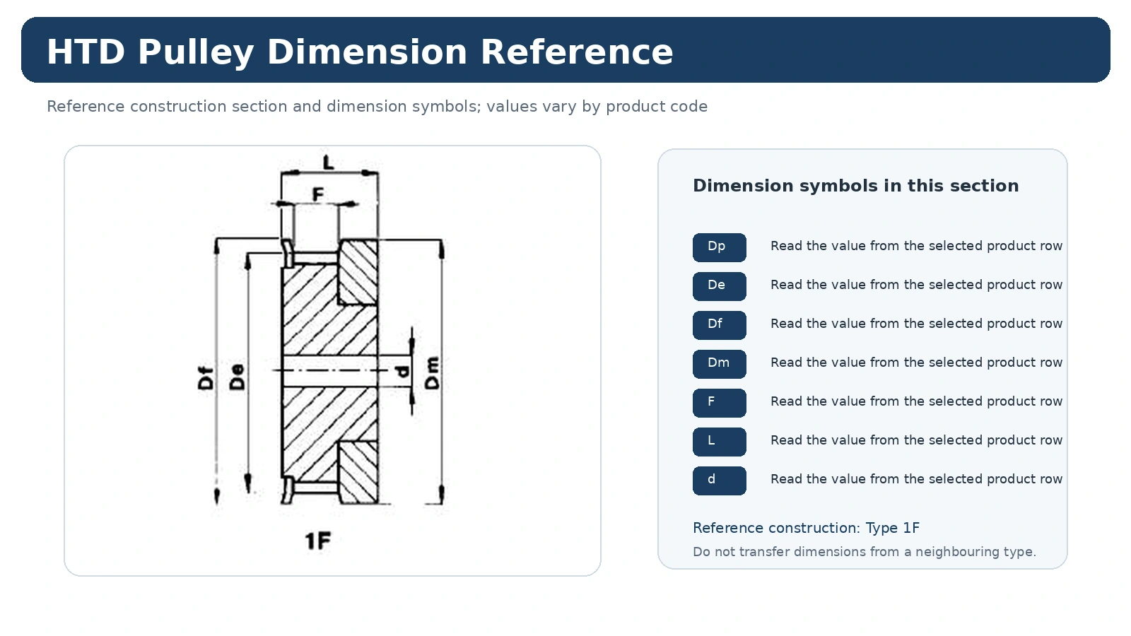
ٹیبل سے پہلے 8M-50 ڈائمینشن ویو پڑھیں
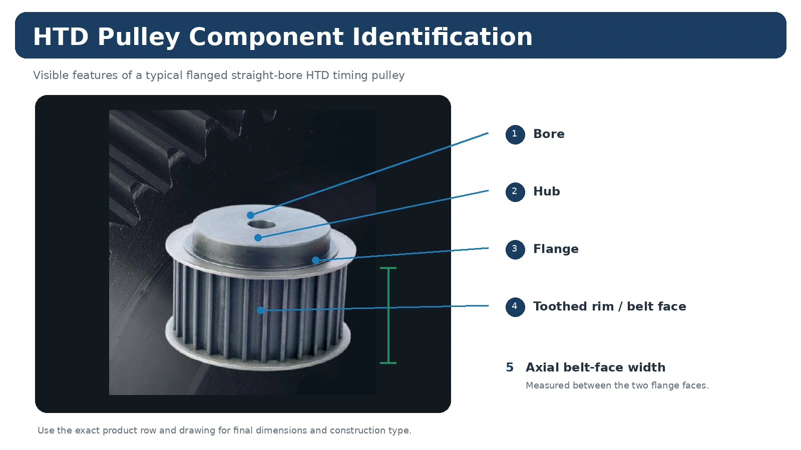
ڈائمینشن ویو اس بات کی وضاحت کرتا ہے کہ ڈی پی، ڈی، ڈی ایف، ڈی ایم، ڈی، ایف، ایل اور بور سے متعلقہ فیلڈز کنسٹرکشن ڈرائنگ سے کیسے متعلق ہیں۔ ڈرائنگ اور ایک ہی مصنوعات کی قطار کو ایک ساتھ استعمال کریں۔ کسی دوسرے تعمیراتی قسم سے طول و عرض کو صرف اس وجہ سے منتقل نہ کریں کہ پچ اور دانتوں کی گنتی مماثل ہے۔
8M-50 کے لیے، وہ اقدار ریکارڈ کریں جو انسٹالیشن کو کنٹرول کرتی ہیں — ورکنگ فیس، ہب پروجیکشن، فلینج لفافہ اور شافٹ کنکشن — ایک مستحکم مشین ڈیٹم کے خلاف۔ اگر ایک تیار شدہ بور، کی وے یا رواداری کی کیٹلاگ قطار کے ذریعے وضاحت نہیں کی گئی ہے، تو اسے عالمی قدر ماننے کے بجائے RFQ یا کنٹرولڈ ڈرائنگ میں شامل کریں۔
8M-50 تکنیکی تفصیلات کی میز
اس سیریز کے لیے منتخب کردہ ٹائمنگ پللی کیٹلاگ سے درج ذیل اقدار کو نقل کیا گیا ہے۔ کوٹیشن کی درخواست کرتے وقت کوڈ اور دانتوں کی گنتی کو ایک ساتھ استعمال کریں۔ طول و عرض کیٹلاگ اقدار ہیں؛ حتمی شافٹ فٹ، کی وے، سطح کی تکمیل اور معائنہ کی ضروریات کو RFQ یا ڈرائنگ پر بیان کیا جانا چاہیے۔
| کوڈ | قسم | دانت | ڈی پی | ڈی | ڈی ایف | ڈی ایم | دی | ایف | ایل | d | فلانج | تقریبا کلو |
|---|---|---|---|---|---|---|---|---|---|---|---|---|
| 22-8M-50 | 2 ایف | 22 | 56,02 | 54,65 | 60 | 43 | – | 60 | 70 | 12 | 308 | 1,10 |
| 24-8M-50 | 2 ایف | 24 | 61,11 | 59,74 | 66 | 45 | – | 60 | 70 | 12 | 310 | 1,30 |
| 26-8M-50 | 2 ایف | 26 | 66,21 | 64,84 | 71 | 48 | – | 60 | 70 | 12 | 311 | 1,60 |
| 28-8M-50 | 2 ایف | 28 | 71,30 | 70,08 | 75 | 50 | – | 60 | 70 | 14 | 312 | 1,70 |
| 30-8M-50 | 2 ایف | 30 | 76,39 | 75,13 | 83 | 55 | – | 60 | 70 | 14 | 314 | 2,00 |
| 32-8M-50 | 2 ایف | 32 | 81,49 | 80,16 | 87 | 60 | – | 60 | 70 | 14 | 315 | 2,35 |
| 34-8M-50 | 2 ایف | 34 | 86,58 | 85,21 | 91 | 66 | – | 60 | 70 | 14 | 316 | 2,80 |
| 36-8M-50 | 2 ایف | 36 | 91,67 | 90,30 | 98,5 | 70 | – | 60 | 70 | 14 | 319 | 3,10 |
| 38-8M-50 | 2 ایف | 38 | 96,77 | 95,39 | 103 | 75 | – | 60 | 70 | 14 | 320 | 3,30 |
| 40-8M-50 | 2 ایف | 40 | 101,86 | 100,49 | 106 | 75 | – | 60 | 70 | 14 | 321 | 3,60 |
| 44-8M-50 | 2 ایف | 44 | 112,05 | 110,67 | 119 | 75 | – | 60 | 70 | 14 | 325 | 4,40 |
| 48-8M-50 | 2 ایف | 48 | 122,23 | 120,86 | 127 | 75 | – | 60 | 70 | 14 | 327 | 5,00 |
| 56-8M-50 | 7 ایف | 56 | 142,60 | 141,23 | 148 | 90 | 116 | 60 | 60 | 18 | 333 | 5,68 |
| 64-8M-50 | 7 ایف | 64 | 162,97 | 161,60 | 168 | 100 | 137 | 60 | 60 | 18 | 338 | 6,93 |
| 72-8M-50 | 7 ایف | 72 | 183,35 | 181,97 | 192 | 100 | 158 | 60 | 60 | 18 | 340 | 7,95 |
| 80-8M-50 | 7 | 80 | 203,72 | 202,35 | – | 110 | 180 | 60 | 60 | 18 | – | 7,96 |
| 90-8M-50 | 7 | 90 | 229,18 | 227,81 | – | 110 | 204 | 60 | 60 | 18 | – | 9,20 |
| 112-8M-50 | 8 | 112 | 285,21 | 283,83 | – | 110 | 254 | 60 | 60 | 18 | – | 12,16 |
| 144-8M-50 | 8 | 144 | 366,69 | 365,32 | – | 110 | 336 | 60 | 60 | 20 | – | 15,68 |
| 168-8M-50 | 8 | 168 | 427,81 | 426,44 | – | 120 | 400 | 60 | 60 | 20 | – | 18,99 |
| 192-8M-50 | 8 | 192 | 488,92 | 487,55 | – | 130 | 460 | 60 | 60 | 20 | – | 24,09 |
جہاں 8M-50 فیملی فٹ بیٹھتی ہے۔
8M-50 صنعتی مطابقت پذیر ڈرائیوز کے لیے استعمال ہونے والی 8M فیملی کا حصہ ہے جہاں دانتوں کی گنتی، تعمیراتی قسم، بور یا جھاڑی اور محوری تنصیب کی جگہ کا ایک ساتھ جائزہ لیا جانا چاہیے۔ درخواست کی مناسبیت کا تعین صرف پچ سے نہیں ہوتا ہے۔ پللی قطار کو حتمی شکل دینے سے پہلے ایک نئی ڈرائیو کو ابھی بھی مطلوبہ رفتار رشتہ، بوجھ یا ٹارک کی بنیاد، مرکز کا فاصلہ، ماحول اور سروس کے حالات کی ضرورت ہے۔
متبادل کے لیے، سب سے محفوظ نقطہ آغاز موجودہ بیلٹ/پروفائل کی شناخت کے علاوہ اصل دانتوں کی گنتی ہے۔ دانتوں کی گنتی کو تبدیل کرنے سے پچ کا قطر اور ڈرائیو کا تناسب بدل جاتا ہے، جب کہ بڑھتے ہوئے کنسٹرکشن کو تبدیل کرنے سے بیلٹ لائن کو حرکت دی جا سکتی ہے یا ہٹانے کی رسائی کو تبدیل کیا جا سکتا ہے۔
8M-50 کے لیے مواد اور تعمیراتی انتخاب
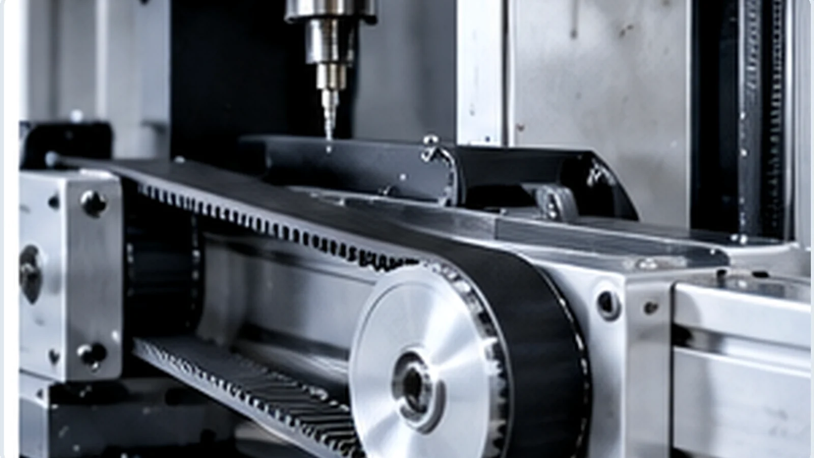
عین مطابق 8M-50 پروڈکٹ کوڈ یا منظور شدہ ڈرائنگ کے لیے دکھایا گیا مواد اور تعمیر استعمال کریں۔ رنگ، سطح کی ظاہری شکل یا تصویر سے گھرنی کے مواد کی شناخت نہ کریں۔ جہاں کوئی پروجیکٹ مختلف مواد، فنش، ہب، فلینج یا شافٹ فیچر کی درخواست کرتا ہے، اسے حسب ضرورت ضرورت سمجھیں اور کوٹیشن سے پہلے طول و عرض اور معائنہ پر اس کے اثر کا جائزہ لیں۔
Within the 22–192 teeth range, construction codes can vary. That variation is why the product code, tooth count and construction view should remain together in the order record.
8M-50 کے لیے انسٹالیشن چیک
انسٹال کرنے سے پہلے، نئی پللی کا ریلیز کردہ 8M-50 قطار یا ڈرائنگ سے موازنہ کریں۔ تناؤ کو لاگو کرنے سے پہلے شافٹ کنکشن، محوری پوزیشن، فلینج کی حالت اور بیلٹ لائن کی تصدیق کریں۔ بیلٹ کو پللی میں داخل ہونا چاہیے بغیر کسی غلط ترتیب والے شافٹ، بے گھر ہونے والے حب یا اسپیسر کے غلط انتظامات کے ذریعے زبردستی کیے بغیر۔
اسمبلی کے بعد، ان خصوصیات کا معائنہ کریں جو اصل مشین کے لیے اہم ہیں—محفوظ ماؤنٹنگ، الائنمنٹ، فری روٹیشن، بیلٹ ٹریکنگ اور کسی بھی ڈرائنگ کے زیر کنٹرول رن آؤٹ یا محوری پوزیشن۔ عام رواداری کا اطلاق نہ کریں جہاں سامان یا آرڈر ڈرائنگ ایک مختلف ضرورت کی وضاحت کرتی ہے۔
آرڈرنگ، نمونے اور کمرشل پلاننگ
کم از کم مقداریں مصنوعات کی قسم، مینوفیکچرنگ روٹ اور کل آرڈر ویلیو کے مطابق مقرر کی جاتی ہیں۔ معیاری کیٹلاگ کے حصے عام طور پر پیداواری مقدار کی کم از کم پیروی کرتے ہیں۔
نئے گاہک 1-5 نمونے کے ٹکڑوں کی درخواست کر سکتے ہیں جب ترتیب اور پیداوار کا راستہ موزوں ہو۔ نمونے الگ سے نقل کیے گئے ہیں۔
گھرنی کے مختلف ماڈلز کو مضبوط کیا جا سکتا ہے۔ تقریباً USD 1,500 کی مشترکہ آرڈر ویلیو مخلوط ماڈل آرڈرز کے لیے معمول کا منصوبہ ہے۔
ایک یا دو ٹکڑوں کی مقدار کو صرف انجینئرنگ کی توثیق یا قابل ادائیگی نمونہ کی ضرورت کے لیے سمجھا جا سکتا ہے، خوردہ آرڈرز کے طور پر نہیں۔ یونٹ کی قیمتیں اسی طرح زیادہ ہیں۔
معیاری حصے: عام طور پر 10-25 کاروباری دن۔ حسب ضرورت اجزاء: عام طور پر 20-45 کاروباری دن۔ پروجیکٹ پر مبنی اسمبلیاں یا متعلقہ سامان: 45-120 کاروباری دن جہاں قابل اطلاق ہوں۔ ڈرائنگ، مواد اور مقدار کا جائزہ لینے کے بعد حتمی وقت کی تصدیق کی جاتی ہے۔
EXW، FOB، CIF اور DAP عام طور پر دستیاب ہیں۔ FCA، CFR، CPT، CIP اور DDP پر مناسب ترسیل اور منازل کے لیے تبادلہ خیال کیا جا سکتا ہے۔
8M-50 کے لیے ایک RFQ کیسے تیار کریں۔
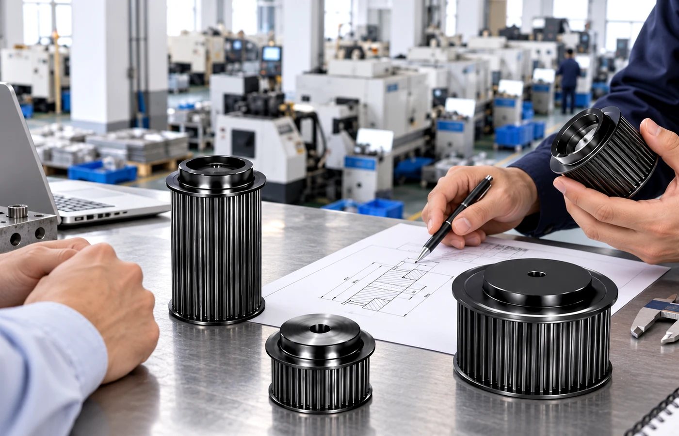
مکمل بیلٹ مارکنگ، مطلوبہ دانتوں کی گنتی، بیلٹ کی چوڑائی، شافٹ کا قطر اور فٹ، بڑھنے کا طریقہ، مقدار اور منزل بھیجیں۔ جب حب پروجیکشن، فلینج جیومیٹری، کی وے، ختم یا معائنہ کی حدیں معیاری نہ ہوں تو ایک جہتی ڈرائنگ یا واضح متبادل تصاویر شامل کریں۔ اگر آپ ایک متروک گھرنی کو تبدیل کر رہے ہیں، تو ایک بیرونی قطر کی قدر پر انحصار کرنے کے بجائے سامنے، پیچھے اور طرف کی پیمائش شامل کریں۔
متعلقہ فیصلوں کے لیے، موازنہ کریں۔ 8M پروڈکٹ فیملیکا جائزہ لیں HTD گھرنی سلیکشن گائیڈ، یا دیکھیں درخواست کی رہنمائی مشین کے مخصوص تحفظات کے لیے۔
8M-50 اکثر پوچھے گئے سوالات
کیا ہر 8M-50 گھرنی قابل تبادلہ ہے؟
نمبر۔ سیریز کا کوڈ پچ اور چوڑائی کے خاندان کو تنگ کرتا ہے، لیکن دانتوں کی گنتی، تعمیراتی قسم، بور یا جھاڑی، حب کے طول و عرض، فلینج کی ترتیب اور مواد مختلف ہو سکتے ہیں۔ عین مطابق کیٹلاگ قطار یا ڈرائنگ کی تصدیق کریں۔
کیا آپ موجودہ گھرنی سے حوالہ دے سکتے ہیں؟
ہاں، بشرطیکہ متبادل معلومات کافی ہو۔ بیلٹ مارکنگ، دانتوں کی گنتی، چہرے کی چوڑائی، شافٹ کی تفصیلات اور دونوں اطراف سے پیمائش بھیجیں۔ غیر معیاری جیومیٹری کے لیے ڈرائنگ کو ترجیح دی جاتی ہے۔
کیا چھوٹی مقدار میں فراہم کی جا سکتی ہے؟
کوالیفائیڈ انجینئرنگ کی توثیق کے لیے چھوٹے ادا شدہ نمونوں پر غور کیا جا سکتا ہے۔ عام فروخت کا راستہ ایک یا دو ٹکڑوں کی خوردہ خریداری کے بجائے صنعتی پیداوار کی فراہمی ہے۔
آرڈر کے ساتھ کن دستاویزات کی درخواست کی جائے؟
ریاست کو آر ایف کیو مرحلے پر جہتی معائنہ، مواد کی دستاویزات، مارکنگ یا آرڈر کے لیے مخصوص تعمیل ریکارڈ کی ضرورت ہے تاکہ پیداوار سے پہلے دستیابی اور دائرہ کار کی تصدیق کی جا سکے۔