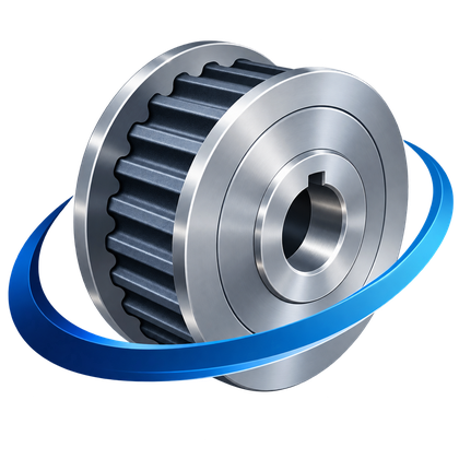
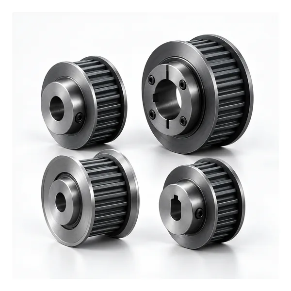
اپنی مرضی کے مطابق HTD ٹائمنگ گھرنی
ڈرائنگ سے طے شدہ بور، حب، فلینج اور معائنہ کی ضروریات کے لیے اپنی مرضی کے مطابق HTD گھرنی مشین۔
Custom HTD Timing Pulley Configuration Overview
اپنی مرضی کے مطابق HTD ٹائمنگ پلیز are intended for projects where the standard tooth family is known but the shaft interface, hub, flange, face width, material or inspection requirement must follow a drawing. The correct workflow starts with the mating belt profile and tooth count, then defines the machine interface around the actual shaft and available envelope.
Define the Tooth System Before the Hub
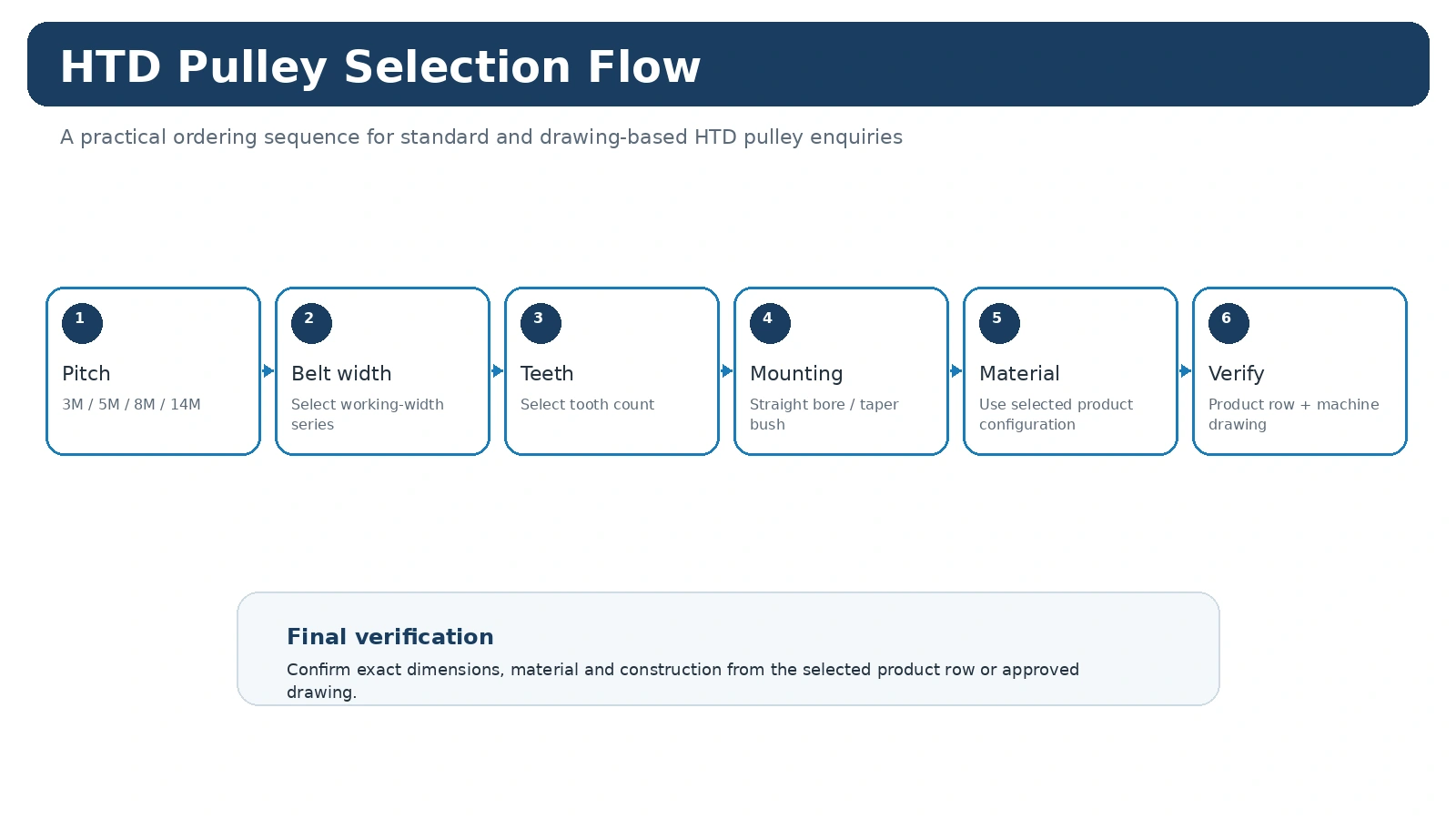
Start with HTD 3M, 5M, 8M or 14M and the required tooth count. Once the belt-side geometry is fixed, the bore, hub projection, keyway or bush arrangement and flange configuration can be reviewed against the machine drawing.
Drawing Inputs for Custom Machining
A useful RFQ identifies pitch, teeth, belt face, shaft diameter and fit, hub geometry, flange arrangement, material, finish, quantity and any controlled runout or inspection requirement. Do not omit the axial reference that locates the belt line relative to the shaft shoulder or bearing face.
Structure and Dimension Review
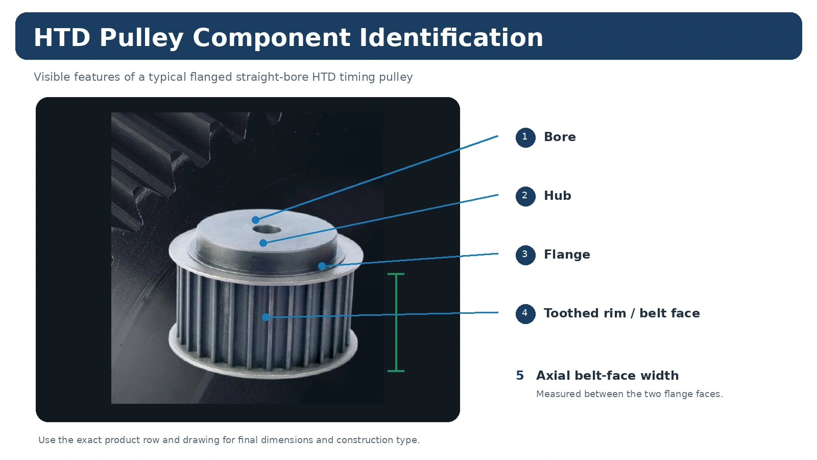
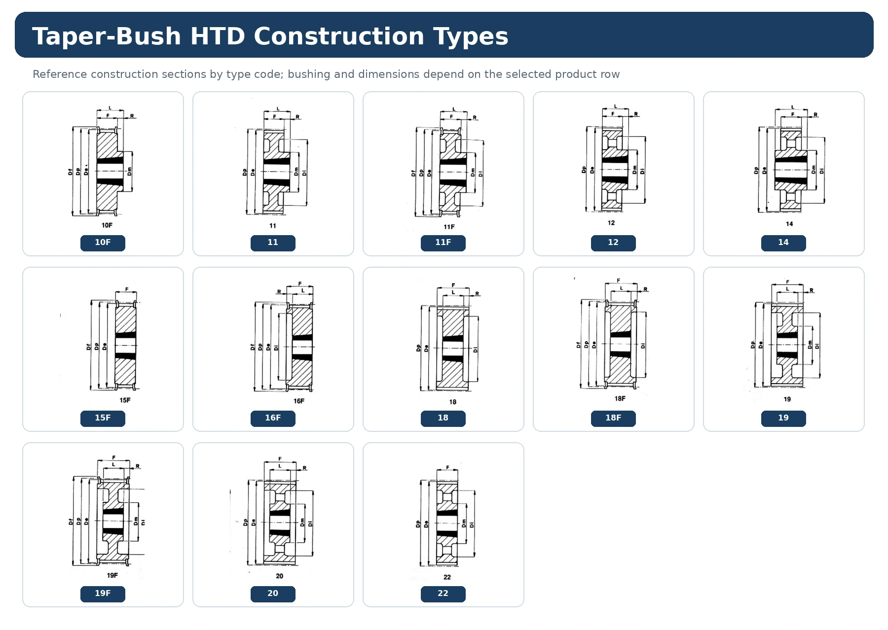
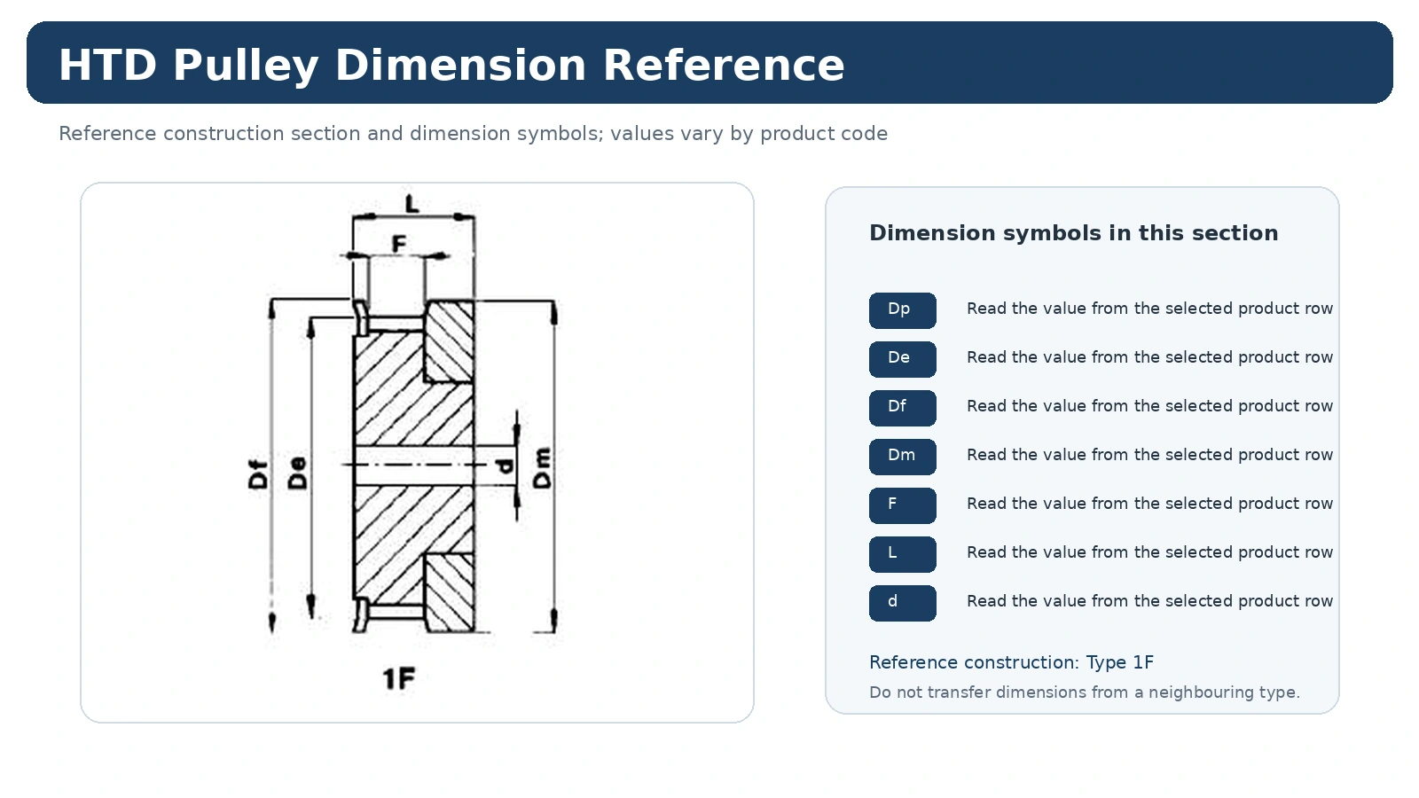
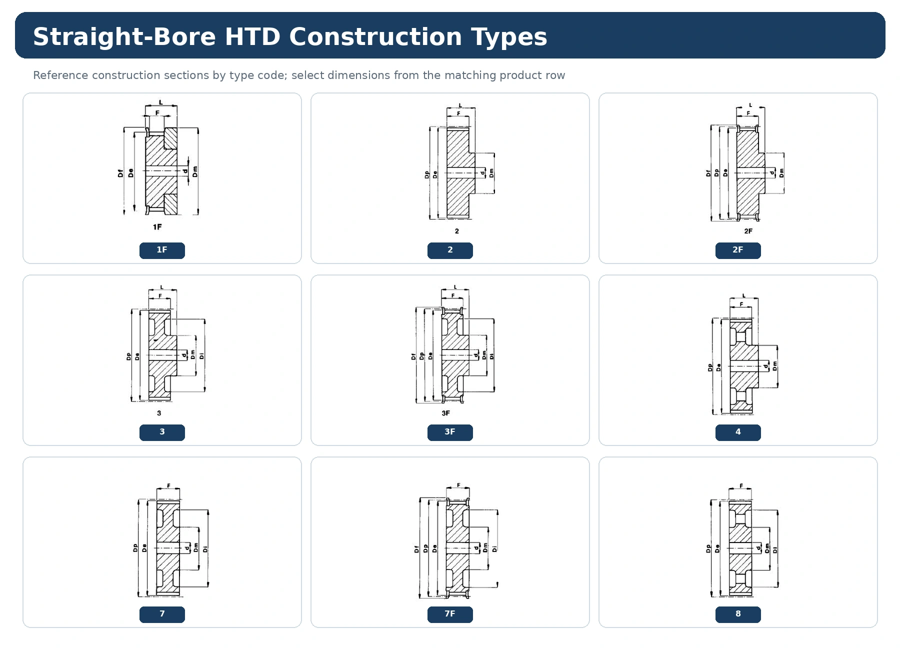
The following references help organize drawing discussions without replacing a final approved drawing. Catalogue section types are useful starting points, but a custom pulley should be manufactured to one controlled geometry rather than a mixture of dimensions taken from several examples.
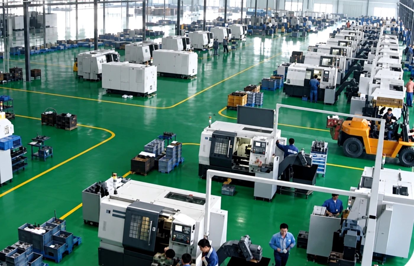
Manufacturing and Inspection Planning
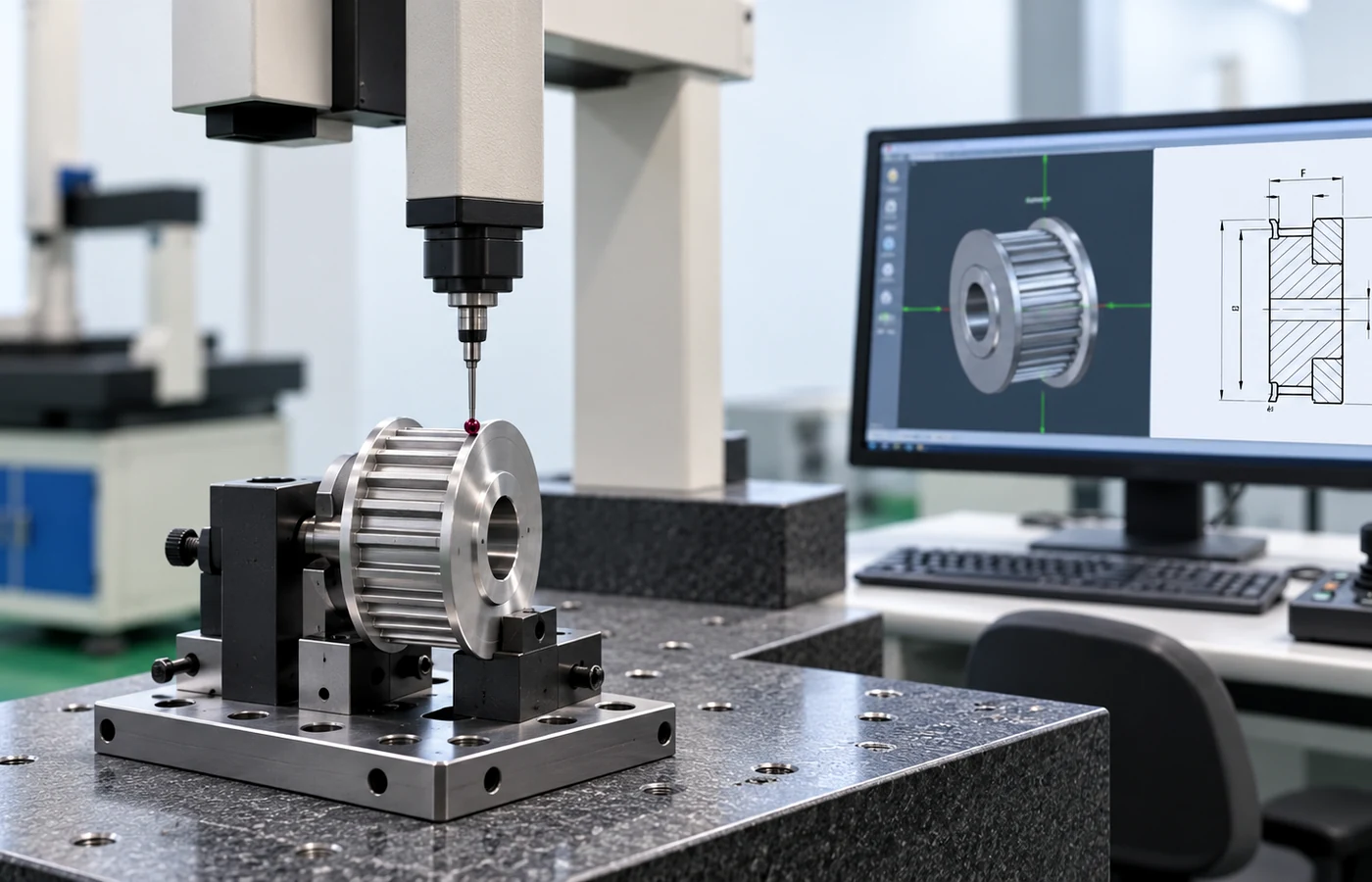
Specify which characteristics are functional: bore fit, keyway location, tooth runout, face width, flange clearance or a datum relationship to another feature. Those controls determine the inspection plan. For repeat orders, keep the approved drawing revision and product identification together so later production does not depend on memory or photographs alone.
آرڈرنگ، نمونے اور کمرشل پلاننگ
کم از کم مقداریں مصنوعات کی قسم، مینوفیکچرنگ روٹ اور کل آرڈر ویلیو کے مطابق مقرر کی جاتی ہیں۔ معیاری کیٹلاگ کے حصے عام طور پر پیداواری مقدار کی کم از کم پیروی کرتے ہیں۔
نئے گاہک 1-5 نمونے کے ٹکڑوں کی درخواست کر سکتے ہیں جب ترتیب اور پیداوار کا راستہ موزوں ہو۔ نمونے الگ سے نقل کیے گئے ہیں۔
گھرنی کے مختلف ماڈلز کو مضبوط کیا جا سکتا ہے۔ تقریباً USD 1,500 کی مشترکہ آرڈر ویلیو مخلوط ماڈل آرڈرز کے لیے معمول کا منصوبہ ہے۔
ایک یا دو ٹکڑوں کی مقدار کو صرف انجینئرنگ کی توثیق یا قابل ادائیگی نمونہ کی ضرورت کے لیے سمجھا جا سکتا ہے، خوردہ آرڈرز کے طور پر نہیں۔ یونٹ کی قیمتیں اسی طرح زیادہ ہیں۔
معیاری حصے: عام طور پر 10-25 کاروباری دن۔ حسب ضرورت اجزاء: عام طور پر 20-45 کاروباری دن۔ پروجیکٹ پر مبنی اسمبلیاں یا متعلقہ سامان: 45-120 کاروباری دن جہاں قابل اطلاق ہوں۔ ڈرائنگ، مواد اور مقدار کا جائزہ لینے کے بعد حتمی وقت کی تصدیق کی جاتی ہے۔
EXW، FOB، CIF اور DAP عام طور پر دستیاب ہیں۔ FCA، CFR، CPT، CIP اور DDP پر مناسب ترسیل اور منازل کے لیے تبادلہ خیال کیا جا سکتا ہے۔
Supplier Qualification and Order Documentation
Third-party supplier audit and company-verification documentation supported by SGS / TÜV Rheinland can be provided for buyer review where applicable to the contracting entity. These materials support review of company identity, business operations, supplier profile and general manufacturing capability; they are not presented as product-specific certification. Product-specific inspection reports, material documents or compliance records can be prepared or supplied according to the confirmed order requirements.
Custom Pulley RFQ Checklist
Send the belt designation, pitch, teeth, face width, shaft/bore requirements, hub and flange geometry, quantity, destination and a dimensioned drawing. Add operating speed, torque/power, center distance and environment for a new drive. See the انتخاب گائیڈ, compare taper-bush options، یا جائزہ لیں۔ معائنہ کی منصوبہ بندی.
Preserve the Standard HTD Tooth Geometry Wherever Possible
A custom pulley is easiest to define when the mating-belt geometry stays standard and only the machine-side features change. State the HTD family, tooth count and working face first, then dimension the bore, keyway or locking interface, hub projection and flange positions. If the project truly needs a nonstandard tooth form, identify the mating belt specification and provide the controlling geometry rather than describing the part only as “custom HTD.”
Keeping standard and custom features separated also simplifies inspection. The standard product family provides a known reference for the belt side; the drawing then shows exactly which dimensions or requirements the project is adding.
Dimension the Installation From Clear Machine Datums
Hub projection and flange location can be as important as the bore because they establish the axial belt line. For replacements, measure both sides of the old pulley and show the shaft shoulder, adjacent bearing or guard surfaces that limit the installation. For new designs, dimension the intended belt centerline from a stable machine datum instead of leaving the axial position to be inferred from an overall width.
If a keyway, clamping feature or taper-mounted interface is required, show the actual shaft size and interface details. Do not specify a generic “finished bore” without the information needed to control how the pulley locates and transmits torque.
Material, Finish and Inspection Are Order-Specific Controls
Choose a material or finish from the real duty, environment and manufacturing route. If corrosion resistance, low inertia, surface protection or a customer material standard is important, state the requirement on the drawing and discuss the available process. Special materials, treatments and coatings can introduce their own minimum batch quantities and lead times.
Inspection requirements should name the characteristic that matters—such as a bore dimension, axial position or specified runout—together with the datum or method when that method is project-controlled. A generic “inspection report required” note is less useful than a short list of the functional characteristics the report must record.
Prototype and Production Revision Control
Small engineering samples are useful only when the successful trial geometry can be reproduced. Put a revision on the drawing used for the sample. If the sample is modified during machine trials, record the change and issue a new revision before production. Do not allow the approved geometry to exist only on a hand-modified prototype.
For mixed-model production, keep each pulley on a separate order line with its drawing revision and quantity. Shared notes for material or documentation can be referenced across the order, but bore and hub details should remain attached to the individual model.
Custom HTD Pulley Commercial Planning
Qualified 1–5 piece samples can be reviewed when the geometry and process are suitable. Mixed models can be combined toward a practical order value of about USD 1,500. Special materials and dedicated processes follow the minimum quantity required by the process. One- or two-piece retail-style replacements are not the standard supply route; very small quantities are considered as qualified engineering validation or paid samples.
Custom components are typically planned within 20–45 business days after the drawing, material and production route are released, subject to quantity and process. EXW, FOB, CIF and DAP are commonly supported, with FCA, CFR, CPT, CIP and DDP available for discussion on suitable shipments. Final timing and terms are confirmed on the quotation.
Review the Custom Geometry From More Than One View
A custom timing pulley should be reviewed from the belt side, shaft side and manufacturing/inspection side. The construction references below are used to identify the family and mounting concept; the released order drawing controls the actual custom dimensions.
Custom HTD Timing Pulley FAQ
What information is most important on a custom drawing?
Keep the HTD profile, tooth count and working width together with the complete shaft interface, hub projection, flange arrangement, material/finish if controlled, and the drawing revision.
Can a standard pulley be remachined?
Sometimes, but only after checking that the standard body leaves enough material and that remachining will not compromise the required hub, wall thickness, belt line or construction. A purpose-made drawing can be safer when several features change.
Can you work from an old pulley?
Yes when the replacement information is sufficient. Photograph the installed drive before disassembly and provide measurements from both faces, the belt marking, tooth count, shaft interface and any known machine changes.
Replacement Projects Need More Than a Loose Sample
A loose old pulley can show tooth count, working face and shaft features, but it may no longer show how the part located inside the machine. Whenever possible, document the installed position before removal. Photograph the shaft shoulder, nearby bearing or guard, belt path and both pulley faces. Add a simple measurement from a fixed machine datum to the belt centerline. This information can expose an axial offset that would be invisible on a bench.
If the old part has no readable code, treat the measurements as reference data rather than guaranteed nominal dimensions. Wear, corrosion and earlier repairs can change what is measured. The replacement drawing should state which values are taken from the old part, which are taken from a standard HTD family, and which are new project requirements.
Design Review Questions Before a Custom Quote
Which HTD family, tooth count and working width must remain compatible with the machine?
What bore, keyway or locking arrangement is required, and where is the belt centerline?
What limits overall diameter, flange position, hub projection and removal space?
Which drawing revision, inspection record, material document or marking must accompany supply?
Answering these questions before quotation reduces late drawing revisions. If a feature is not controlled by the machine or customer specification, it does not need an unnecessarily tight tolerance or special process.
Final Drawing Release
Before production, confirm that quotation, drawing revision and purchase order identify the same configuration. If customer approval is required, complete that approval before machining the project-specific interface. This keeps prototype, production and future replacement records aligned.
Drawing Inputs That Reduce Rework
Define the belt-side geometry and shaft-side geometry on the same controlled drawing. Keep HTD pitch, tooth count and working width explicit, then add the bore or bush, keyway, hub projection, flange arrangement and any installation-critical axial dimensions. If a tolerance, finish or inspection record is required, identify the exact feature and datum rather than applying a blanket “precision” note to the entire part.
For replacement projects, include photographs and measurements from both sides of the installed pulley. For new designs, include the shaft and surrounding envelope so the custom hub does not move the belt line into a guard, bearing housing or adjacent component. One approved drawing revision should control quotation, machining and inspection.