एचटीडी 14एम-115 टाइमिंग पुली
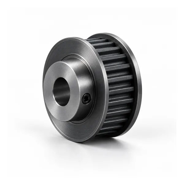
14M वक्ररेखीय सिंक्रोनस टाइमिंग पुली, 14M-115 श्रृंखला। कैटलॉग तालिका या अनुमोदित चित्र से दांतों की संख्या, बेल्ट की चौड़ाई और शाफ्ट इंटरफ़ेस का चयन करें।
HTD 14M-115 टाइमिंग पुली कॉन्फ़िगरेशन का अवलोकन
14M-115 HTD टाइमिंग पुली यह 14 मिमी पिच वाली सिंक्रोनस पुली फैमिली है, जिसका कैटलॉग नामकरण प्रणाली में नाममात्र बेल्ट-फेस संदर्भ 115 है। यह पृष्ठ इस सीरीज़ को एक निश्चित SKU के बजाय एक कॉन्फ़िगर करने योग्य औद्योगिक घटक के रूप में मानता है। दांतों की संख्या पुली के व्यास को बदलती है और इससे हब, फ्लेंज, सामग्री या माउंटिंग विवरण भी बदल सकते हैं, इसलिए ऑर्डर को किसी विशिष्ट कैटलॉग पंक्ति या अनुमोदित ड्राइंग से जोड़ा जाना चाहिए।
खरीद के लिए, सबसे पहले बेल्ट का पूरा नाम देखें और पुष्टि करें कि मिलान करने वाली बेल्ट उसी HTD 14M प्रोफाइल का उपयोग करती है। केवल पिच के आधार पर सभी घुमावदार बेल्टों के लिए सुरक्षित अदला-बदली का नियम नहीं है। प्रोफाइल की पुष्टि के बाद, दांतों की संख्या और कार्य चौड़ाई चुनें, फिर शाफ्ट इंटरफ़ेस, हब प्रोजेक्शन, फ्लेंज व्यवस्था और उपलब्ध सामग्री की समीक्षा करें। यह प्रक्रिया केवल बाहरी व्यास का मिलान करने और दांतों की प्रणाली या माउंटिंग ज्यामिति को नज़रअंदाज़ करने की आम त्रुटि को कम करती है।
इस श्रेणी के लिए प्रदर्शित सीधी बोर वाली संरचना सकारात्मक सिंक्रोनस पावर ट्रांसमिशन के लिए बनाई गई है। आमतौर पर बड़े औद्योगिक ड्राइव, कपड़ा/कागज मशीनरी और भारी सिंक्रोनस ट्रांसमिशन से संबंधित पूछताछ आती है। वास्तविक उपयुक्तता गति, प्रेषित भार, केंद्र दूरी, बेल्ट संरचना, संरेखण, वातावरण और शाफ्ट सपोर्ट पर निर्भर करती है। ये आवश्यक इनपुट नए ड्राइव के लिए या जब किसी मौजूदा मशीन में बेल्ट ट्रैकिंग या घिसाव की समस्या बार-बार हो रही हो, तब प्रदान किए जाने चाहिए।
14एम-115 निर्माण और शाफ्ट इंटरफ़ेस
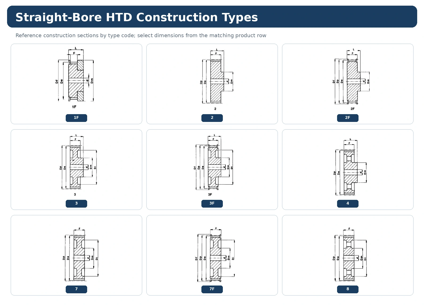
14एम-115 यह 14M HTD परिवार से संबंधित है और यह पृष्ठ स्ट्रेट-बोर निर्माण को कवर करता है। इस पृष्ठ पर कैटलॉग तालिका 28 से 192 दांतों तक की रेंज को दर्शाती है। तालिका में दिखाई देने वाले निर्माण कोड में 2F, 7F और 8 शामिल हैं। दांतों की संख्या के साथ सटीक उत्पाद कोड का उपयोग करें क्योंकि हब/फ्लेंज व्यवस्था एक ही चौड़ाई श्रृंखला के भीतर बदल सकती है।
चौड़ाई कोड 115 यह कैटलॉग परिवार की पहचान करता है; यह बेल्ट मार्किंग और आयाम ड्राइंग की जाँच का विकल्प नहीं है। प्रतिस्थापन कार्य के लिए, स्थापित बेल्ट लाइन को सुरक्षित रखें और सही दांतों वाली पंक्ति को यांत्रिक विकल्प मानने से पहले शाफ्ट-साइड ज्यामिति को मापें।
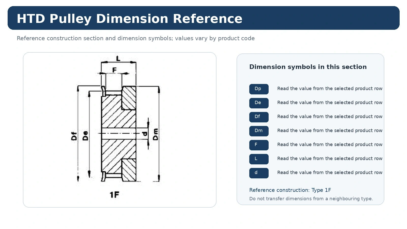
टेबल लगाने से पहले 14M-115 आयाम दृश्य पढ़ें
डाइमेंशन व्यू यह बताता है कि Dp, De, Df, Dm, Di, F, L जैसे सिंबल और बोर से संबंधित फ़ील्ड कंस्ट्रक्शन ड्राइंग से कैसे संबंधित हैं। ड्राइंग और एक ही प्रोडक्ट रो का एक साथ उपयोग करें; केवल पिच और दांतों की संख्या मेल खाने के कारण किसी अन्य कंस्ट्रक्शन टाइप से डाइमेंशन को ट्रांसफर न करें।
14M-115 के लिए, स्थिर मशीन डेटम के आधार पर इंस्टॉलेशन को नियंत्रित करने वाले मानों (कार्यशील सतह, हब प्रोजेक्शन, फ्लेंज एनवेलप और शाफ्ट कनेक्शन) को रिकॉर्ड करें। यदि कैटलॉग पंक्ति में फिनिश्ड बोर, कीवे या टॉलरेंस परिभाषित नहीं है, तो सार्वभौमिक मान मानने के बजाय इसे RFQ या नियंत्रित ड्राइंग में जोड़ें।
14एम-115 तकनीकी विशिष्टता तालिका
निम्नलिखित मान इस श्रृंखला के लिए चयनित टाइमिंग-पुली कैटलॉग से लिए गए हैं। कोटेशन का अनुरोध करते समय कोड और दांतों की संख्या दोनों का एक साथ उपयोग करें। आयाम कैटलॉग मान हैं; अंतिम शाफ्ट फिट, कीवे, सतह की फिनिश और निरीक्षण संबंधी आवश्यकताओं को आरएफक्यू या ड्राइंग पर स्पष्ट रूप से बताया जाना चाहिए।
| कोड | प्रकार | दाँत | डी पी | दे | डीएफ | डीएम | डि | एफ | एल | डी | निकला हुआ | लगभग किलोग्राम |
|---|---|---|---|---|---|---|---|---|---|---|---|---|
| 28-14एम-115 | 2F | 28 | 124,78 | 122,12 | 127 | 100 | – | 133 | 148 | 32 | 400 | 10,75 |
| 30-14एम-115 | 2F | 30 | 133,69 | 130,99 | 138 | 100 | – | 133 | 148 | 32 | 401 | 12,52 |
| 32-14एम-115 | 2F | 32 | 142,60 | 139,88 | 154 | 100 | – | 133 | 148 | 32 | 403 | 14,48 |
| 34-14एम-115 | 2F | 34 | 151,52 | 148,79 | 160 | 100 | – | 133 | 148 | 32 | 404 | 16,45 |
| 36-14एम-115 | 2F | 36 | 160,43 | 157,68 | 168 | 120 | – | 133 | 148 | 32 | 405 | 18,99 |
| 38-14एम-115 | 2F | 38 | 169,34 | 166,60 | 183 | 120 | – | 133 | 148 | 32 | 406 | 21,31 |
| 40-14एम-115 | 2F | 40 | 178,25 | 175,49 | 188 | 135 | – | 133 | 148 | 32 | 407 | 24,04 |
| 44-14एम-115 | 2F | 44 | 196,08 | 193,28 | 211 | 140 | – | 133 | 148 | 32 | 411 | 29,41 |
| 48-14एम-115 | 2F | 48 | 213,90 | 211,11 | 226 | 150 | – | 133 | 148 | 32 | 412 | 35,00 |
| 56-14एम-115 | 2F | 56 | 249,55 | 246,76 | 256 | 150 | – | 133 | 148 | 32 | 416 | 48,00 |
| 64-14एम-115 | 7F | 64 | 285,21 | 282,41 | 296 | 150 | 240 | 133 | 133 | 32 | 418 | 36,00 |
| 72-14एम-115 | 8 | 72 | 320,86 | 318,06 | – | 150 | 278 | 133 | 133 | 32 | 36,00 | |
| 80-14एम-115 | 8 | 80 | 356,51 | 353,71 | – | 150 | 314 | 133 | 133 | 32 | – | 40,00 |
| 90-14एम-115 | 8 | 90 | 401,07 | 398,28 | – | 150 | 358 | 133 | 133 | 32 | – | 45,00 |
| 112-14एम-115 | 8 | 112 | 499,11 | 496,32 | – | 150 | 456 | 133 | 133 | 32 | – | 55,50 |
| 144-14एम-115 | 8 | 144 | 641,71 | 638,92 | – | 165 | 600 | 133 | 133 | 32 | – | |
| 168-14एम-115 | 8 | 168 | 748,66 | 745,87 | – | 165 | 706 | 133 | 133 | 32 | ||
| 192-14एम-115 | 8 | 192 | 855,62 | 852,82 | – | 165 | 813 | 133 | 133 | 32 | – |
14M-115 परिवार कहाँ फिट बैठता है
14M-115, 14M परिवार का हिस्सा है जिसका उपयोग बड़े HTD ड्राइव एनवेलप के लिए किया जाता है, जहाँ हब, फ्लेंज, शाफ्ट इंटरफ़ेस, द्रव्यमान और सर्विस एक्सेस इंस्टॉलेशन प्लानिंग में तेजी से महत्वपूर्ण हो जाते हैं। अनुप्रयोग की उपयुक्तता केवल पिच से निर्धारित नहीं होती है। पुली पंक्ति को अंतिम रूप देने से पहले, एक नए ड्राइव के लिए आवश्यक गति संबंध, लोड या टॉर्क आधार, केंद्र दूरी, पर्यावरण और सर्विस स्थितियों की आवश्यकता होती है।
किसी बेल्ट को बदलने के लिए, सबसे सुरक्षित शुरुआती बिंदु मौजूदा बेल्ट/प्रोफ़ाइल की पहचान और मूल दांतों की संख्या है। दांतों की संख्या बदलने से पिच व्यास और ड्राइव अनुपात बदल जाता है, जबकि माउंटिंग संरचना बदलने से बेल्ट की दिशा बदल सकती है या उसे निकालने की प्रक्रिया में बदलाव आ सकता है।
14M-115 के लिए सामग्री और निर्माण विकल्प
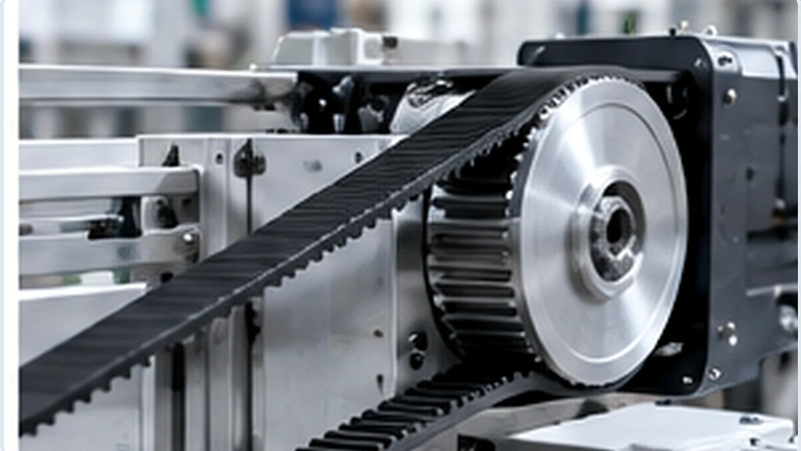
14M-115 उत्पाद कोड या स्वीकृत ड्राइंग के लिए दिखाए गए मटेरियल और निर्माण का ही उपयोग करें। पुली के मटेरियल की पहचान रंग, सतह की बनावट या फोटो से न करें। यदि किसी प्रोजेक्ट में अलग मटेरियल, फिनिश, हब, फ्लेंज या शाफ्ट की विशेषता की आवश्यकता हो, तो उसे कस्टम आवश्यकता मानें और कोटेशन देने से पहले आयामों और निरीक्षण पर इसके प्रभाव की समीक्षा करें।
28 से 192 दांतों की सीमा के भीतर, निर्माण कोड भिन्न हो सकते हैं। इसी भिन्नता के कारण ऑर्डर रिकॉर्ड में उत्पाद कोड, दांतों की संख्या और निर्माण दृश्य एक साथ होने चाहिए।
14M-115 के लिए इंस्टॉलेशन जांच
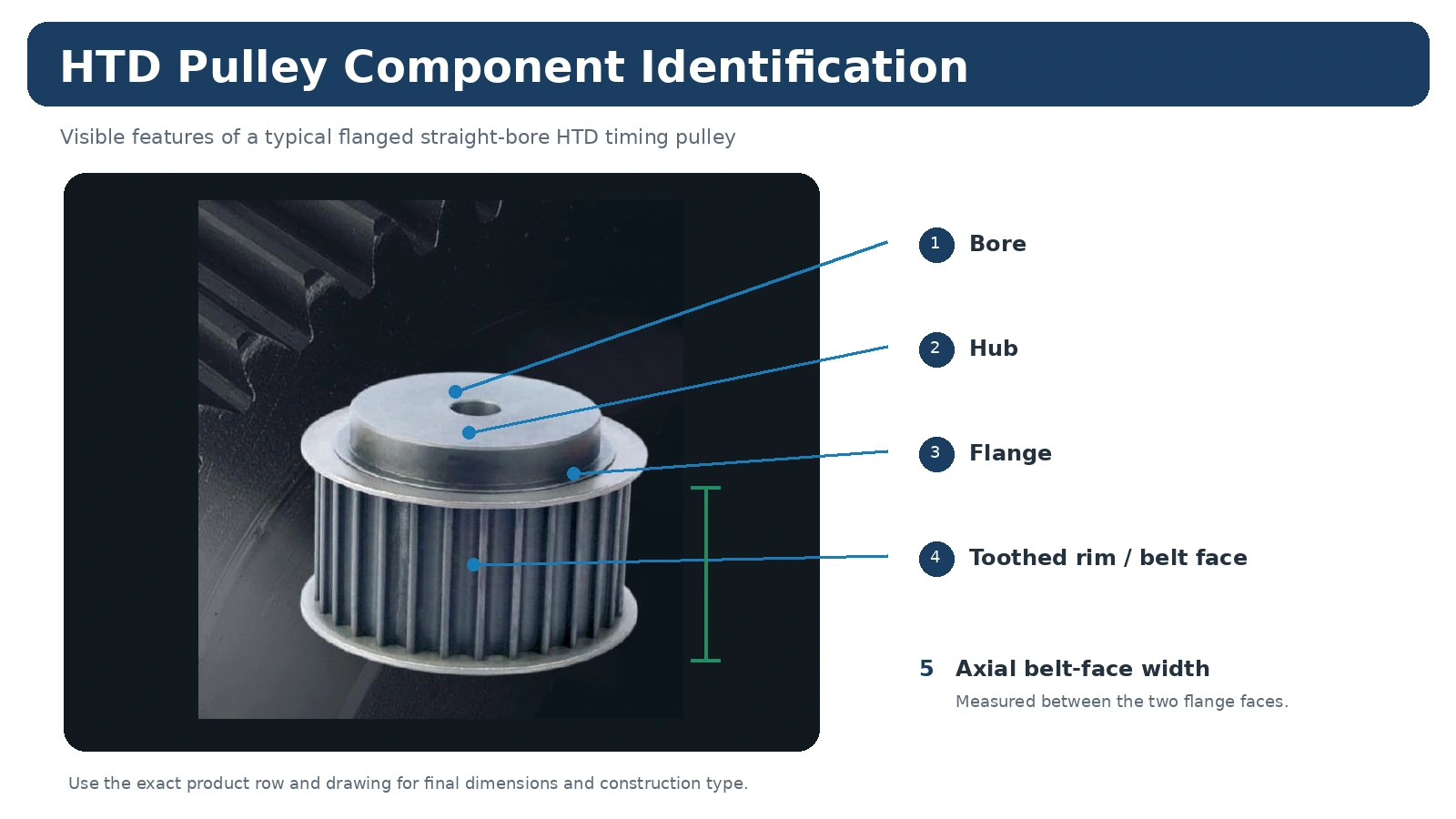
स्थापना से पहले, नई पुली की तुलना जारी किए गए 14M-115 पंक्ति या चित्र से करें। तनाव लगाने से पहले शाफ्ट कनेक्शन, अक्षीय स्थिति, फ्लेंज की स्थिति और बेल्ट लाइन की जाँच करें। बेल्ट को पुली में इस तरह से प्रवेश करना चाहिए कि शाफ्ट के गलत संरेखण, हब के विस्थापन या गलत स्पेसर व्यवस्था के कारण उसे अगल-बगल धकेला न जाए।
असेंबली के बाद, मशीन के वास्तविक संचालन से संबंधित महत्वपूर्ण विशेषताओं की जांच करें—सुरक्षित माउंटिंग, संरेखण, सुचारू घूर्णन, बेल्ट ट्रैकिंग और ड्राइंग में निर्धारित रनआउट या अक्षीय स्थिति। जहां उपकरण या ऑर्डर ड्राइंग में कोई भिन्न आवश्यकता बताई गई हो, वहां सामान्य टॉलरेंस लागू न करें।
ऑर्डर देना, नमूने प्राप्त करना और व्यावसायिक योजना बनाना
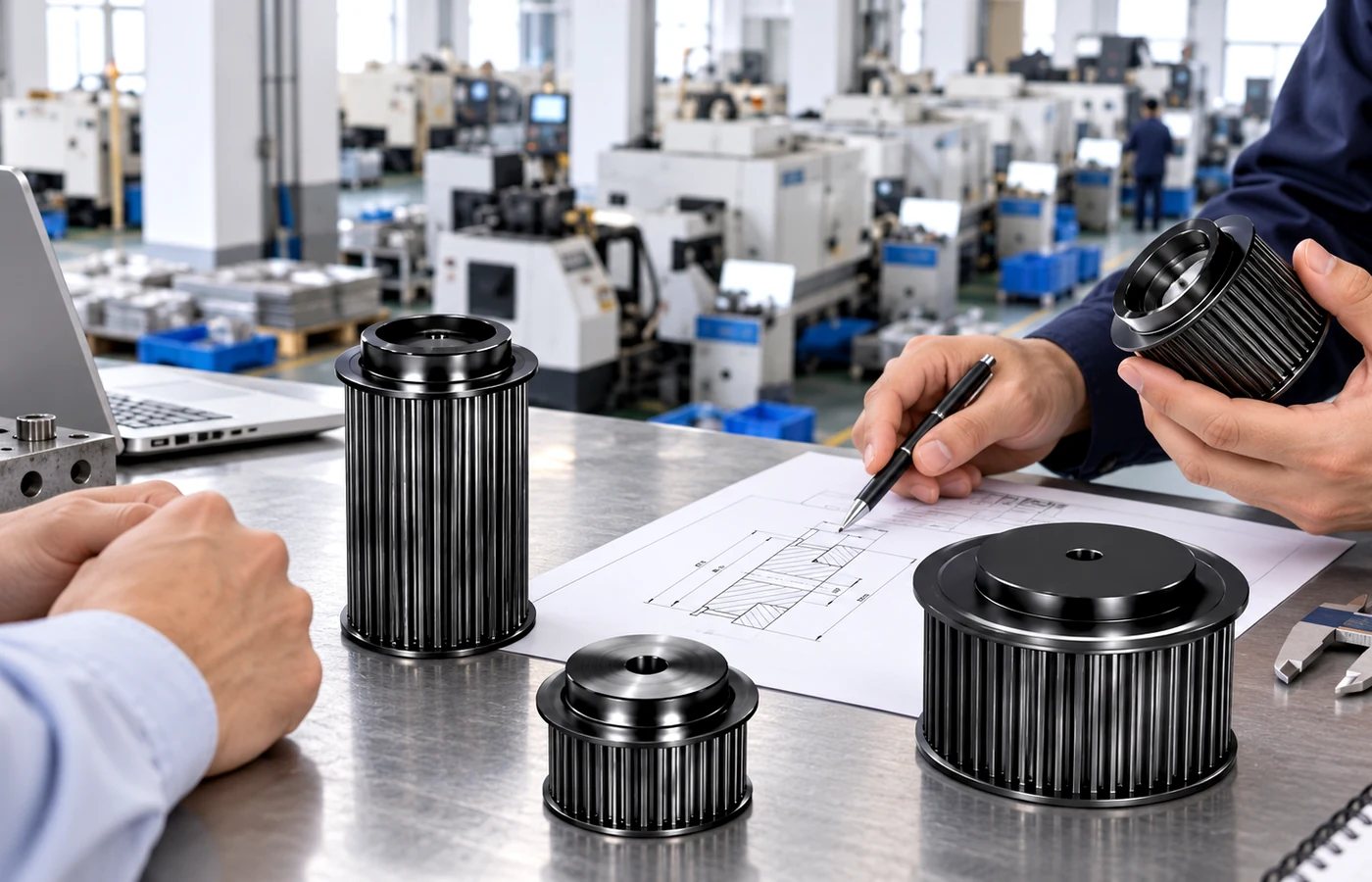
उत्पाद के प्रकार, निर्माण प्रक्रिया और कुल ऑर्डर मूल्य के अनुसार न्यूनतम मात्रा निर्धारित की जाती है। मानक कैटलॉग पार्ट्स आमतौर पर उत्पादन-मात्रा की न्यूनतम सीमा का पालन करते हैं।
यदि कॉन्फ़िगरेशन और उत्पादन प्रक्रिया उपयुक्त हो तो नए ग्राहक 1-5 नमूने मंगवा सकते हैं। नमूनों की कीमत अलग से बताई जाएगी।
विभिन्न पुली मॉडलों को समेकित किया जा सकता है। मिश्रित मॉडल ऑर्डर के लिए आमतौर पर लगभग 1,500 अमेरिकी डॉलर का संयुक्त ऑर्डर मूल्य निर्धारित किया जाता है।
एक या दो पीस की मात्रा पर केवल इंजीनियरिंग सत्यापन या किसी योग्य सशुल्क नमूने की आवश्यकता के लिए ही विचार किया जा सकता है, खुदरा ऑर्डर के रूप में नहीं; इसके लिए प्रति यूनिट मूल्य तदनुसार अधिक होता है।
मानक पुर्जे: आमतौर पर 10-25 कार्यदिवस। कस्टम पुर्जे: आमतौर पर 20-45 कार्यदिवस। परियोजना-आधारित असेंबली या संबंधित उपकरण: 45-120 कार्यदिवस (जहां लागू हो)। अंतिम समय की पुष्टि ड्राइंग, सामग्री और मात्रा की समीक्षा के बाद की जाती है।
EXW, FOB, CIF और DAP आमतौर पर उपलब्ध हैं। उपयुक्त शिपमेंट और गंतव्यों के लिए FCA, CFR, CPT, CIP और DDP पर चर्चा की जा सकती है।
14M-115 के लिए RFQ कैसे तैयार करें
बेल्ट की पूरी मार्किंग, आवश्यक दांतों की संख्या, बेल्ट की चौड़ाई, शाफ्ट का व्यास और फिट, माउंटिंग विधि, मात्रा और गंतव्य स्थान भेजें। यदि हब प्रोजेक्शन, फ्लेंज ज्यामिति, कीवे, फिनिश या निरीक्षण सीमाएं मानक नहीं हैं, तो आयाम सहित ड्राइंग या स्पष्ट प्रतिस्थापन तस्वीरें संलग्न करें। यदि आप अप्रचलित पुली को बदल रहे हैं, तो केवल एक बाहरी व्यास मान पर निर्भर रहने के बजाय आगे, पीछे और पार्श्व माप शामिल करें।
संबंधित निर्णयों के लिए, तुलना करें 14M उत्पाद परिवारसमीक्षा करें एचटीडी पुली चयन गाइडया देखें आवेदन संबंधी मार्गदर्शन मशीन संबंधी विशिष्ट विचारों के लिए।
14M-115 अक्सर पूछे जाने वाले प्रश्न
क्या 14M-115 की सभी पुली एक दूसरे के साथ बदली जा सकती हैं?
नहीं। सीरीज़ कोड पिच और चौड़ाई के प्रकार को सीमित करता है, लेकिन दांतों की संख्या, निर्माण प्रकार, बोर या बुश, हब के आयाम, फ्लेंज की व्यवस्था और सामग्री भिन्न हो सकती है। कृपया कैटलॉग पंक्ति या चित्र की सटीक जानकारी की पुष्टि करें।
क्या आप किसी मौजूदा पुली से उद्धरण दे सकते हैं?
जी हां, बशर्ते प्रतिस्थापन संबंधी जानकारी पर्याप्त हो। बेल्ट मार्किंग, दांतों की संख्या, फेस की चौड़ाई, शाफ्ट का विवरण और दोनों तरफ से माप भेजें। गैर-मानक ज्यामिति के लिए ड्राइंग को प्राथमिकता दी जाएगी।
क्या कम मात्रा में आपूर्ति की जा सकती है?
योग्य इंजीनियरिंग सत्यापन के लिए छोटे सशुल्क नमूनों पर विचार किया जा सकता है। बिक्री का सामान्य तरीका खुदरा खरीद के बजाय औद्योगिक उत्पादन आपूर्ति है।
ऑर्डर के साथ कौन-कौन से दस्तावेज़ मांगे जाने चाहिए?
राज्य द्वारा आवश्यक आयामी निरीक्षण, सामग्री प्रलेखन, अंकन या ऑर्डर-विशिष्ट अनुपालन रिकॉर्ड को आरएफक्यू चरण में ही प्रस्तुत किया जाना चाहिए ताकि उत्पादन से पहले उपलब्धता और दायरे की पुष्टि की जा सके।