HTD 5M Timing Pulley Selection Guide should be approached as a drive-system decision. The useful starting point is the mating belt and machine interface, followed by tooth count, working width, shaft mounting and duty conditions. This guide explains the checks that help an engineer or buyer turn HTD 5M timing pulley selection into an RFQ that can be verified against a catalogue row or drawing.
आयामों की तुलना करने से पहले ड्राइव की पहचान करें
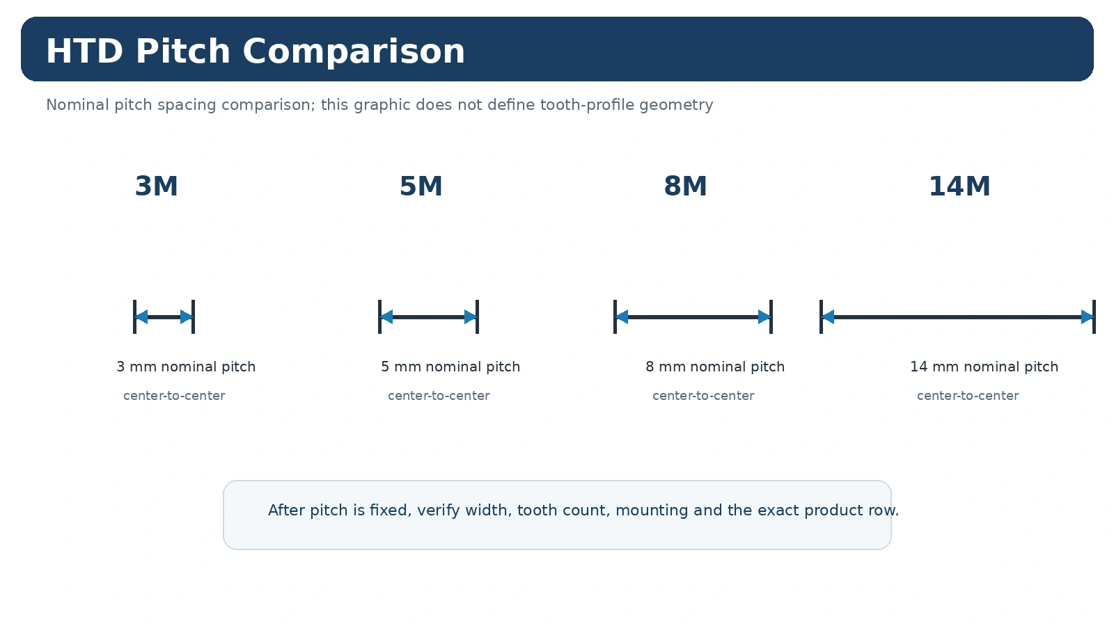
For HTD 5M timing pulley selection, identify the complete belt marking before comparing pulley diameters. HTD is a curvilinear synchronous system and the nominal pitch must stay associated with its profile family. Record the driver and driven tooth counts when an existing ratio must be preserved. For a new drive, document the target speed ratio, driver speed and expected load before choosing tooth counts. This prevents a component-level decision from overriding the machine requirement.
किसी प्रतिस्थापन परियोजना के लिए, कैटलॉग पंक्ति को समतुल्य मानने से पहले मापे गए मान की तुलना स्थापित बेल्ट और मशीन व्यवस्था से करें। किसी नई परियोजना के लिए, डिज़ाइन आधार को दस्तावेज़ित करें ताकि बाद में रखरखाव करने वाली टीमें समझ सकें कि पिच, दांतों की संख्या और माउंटिंग शैली का चयन क्यों किया गया था।
वे आयाम जो स्थापना को नियंत्रित करते हैं
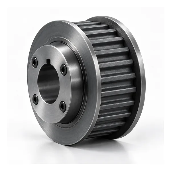
पिच और दांतों की संख्या मेल खाने के बावजूद भी पुली मशीन में फिट नहीं हो सकती क्योंकि बोर, हब, फ्लेंज या अक्षीय स्थिति भिन्न हो सकती है। शाफ्ट इंटरफ़ेस, बेल्ट-फेस की चौड़ाई, दोनों तरफ हब प्रोजेक्शन और एक स्थिर मशीन डेटम के सापेक्ष बेल्ट लाइन को मापें। यदि टेपर बुश का उपयोग किया जाता है, तो पुली सीरीज़ और बुश कोड दोनों को रिकॉर्ड करें। यदि फिनिश्ड बोर की आवश्यकता है, तो ड्राइंग में फिट, कीवे और किसी भी रिटेनिंग विधि को शामिल करें।
किसी प्रतिस्थापन परियोजना के लिए, कैटलॉग पंक्ति को समतुल्य मानने से पहले मापे गए मान की तुलना स्थापित बेल्ट और मशीन व्यवस्था से करें। किसी नई परियोजना के लिए, डिज़ाइन आधार को दस्तावेज़ित करें ताकि बाद में रखरखाव करने वाली टीमें समझ सकें कि पिच, दांतों की संख्या और माउंटिंग शैली का चयन क्यों किया गया था।
चयन में शामिल परिचालन स्थितियाँ
The same nominal HTD 5M timing pulley selection component can see very different service depending on the machine. Starts per hour, reversing, shock loading, continuous operating time, temperature, contamination, cleaning and access for tensioning all influence the drive. A compact automation axis emphasizes repeatable motion and controlled alignment, while a conveyor or process machine may emphasize continuous duty and service access. Supply these conditions instead of asking the pulley to be selected from size alone.
किसी प्रतिस्थापन परियोजना के लिए, कैटलॉग पंक्ति को समतुल्य मानने से पहले मापे गए मान की तुलना स्थापित बेल्ट और मशीन व्यवस्था से करें। किसी नई परियोजना के लिए, डिज़ाइन आधार को दस्तावेज़ित करें ताकि बाद में रखरखाव करने वाली टीमें समझ सकें कि पिच, दांतों की संख्या और माउंटिंग शैली का चयन क्यों किया गया था।
स्थापना से पहले निरीक्षण बिंदु
निरीक्षण में ड्राइव को प्रभावित करने वाले आयामों पर ध्यान केंद्रित किया जाना चाहिए: शाफ्ट इंटरफ़ेस, अक्षीय स्थिति, दांतों की स्थिति, फेस की चौड़ाई और ड्राइंग द्वारा नियंत्रित कोई भी रनआउट या डेटम संबंध। एक सामान्य गुणवत्ता विवरण स्वीकृति को परिभाषित नहीं करता है। यदि आयामी रिपोर्ट, सामग्री दस्तावेज़ या ऑर्डर-विशिष्ट रिकॉर्ड की आवश्यकता है, तो उत्पादन से पहले इसकी पहचान करें। रखरखाव के दौरान, फ्लेंज क्षति, किनारे की घिसावट, मलबा और शाफ्ट पर पुली के हिलने के संकेतों पर ध्यान दें।
किसी प्रतिस्थापन परियोजना के लिए, कैटलॉग पंक्ति को समतुल्य मानने से पहले मापे गए मान की तुलना स्थापित बेल्ट और मशीन व्यवस्था से करें। किसी नई परियोजना के लिए, डिज़ाइन आधार को दस्तावेज़ित करें ताकि बाद में रखरखाव करने वाली टीमें समझ सकें कि पिच, दांतों की संख्या और माउंटिंग शैली का चयन क्यों किया गया था।
ऑर्डर देने से पहले बंद करने के लिए खुले प्रश्न
स्थापित या निर्दिष्ट एचटीडी प्रोफाइल और चौड़ाई कितनी है?
दांतों की मौजूदा संख्या का कौन सा अनुपात या संख्या संरक्षित किया जाना चाहिए?
किस प्रकार के बोर, फिट, कीवे या टेपर-बुश अरेंजमेंट की आवश्यकता है?
हब प्रोजेक्शन और फ्लेंज क्लीयरेंस के लिए कितनी जगह उपलब्ध है?
इसकी गति, भार, शुरुआत, रिवर्सिंग और परिचालन घंटे क्या-क्या हैं?
आपूर्ति के साथ कौन-कौन से चित्र, सामग्री या निरीक्षण संबंधी दस्तावेज संलग्न होने चाहिए?
आरएफक्यू के साथ क्या भेजें
प्रोफ़ाइल, दांतों की संख्या, बेल्ट की चौड़ाई, शाफ़्ट इंटरफ़ेस, हब/फ्लेंज विवरण, मात्रा, गंतव्य और एक ड्राइंग या प्रतिस्थापन माप रेखाचित्र भेजें। नए ड्राइव के लिए गति, अनुपात, भार, केंद्र दूरी और वातावरण जोड़ें। समीक्षा करें। एचटीडी उत्पाद परिवार, उपयोग चयन मार्गदर्शिकाया प्रासंगिक की तुलना करें आवेदन टिप्पणी.
5M Selection Priorities
The 5M family on this site is organised as 5M-09, 5M-15 and 5M-25. Begin with the mating HTD 5M belt, then choose the width series and tooth-count row before defining the shaft interface.
मापित मानों, कैटलॉग संदर्भों और परियोजना आवश्यकताओं को स्पष्ट रूप से अलग रखें। यदि कोई आवश्यक बिंदु संबंधित कैटलॉग तालिका या अनुमोदित चित्र में उल्लिखित नहीं है, तो उसे किसी संभावित लेकिन असत्यापित मान से भरने के बजाय, उसे आरएफक्यू प्रश्न या चित्र आवश्यकता के रूप में शामिल करें।
Do Not Treat Width Series as a Cosmetic Suffix
The width series changes the usable belt face and can change the construction details shown in the table. Keep it in the product code and RFQ rather than asking for a generic “5M pulley”.
खरीद रिकॉर्ड में मशीन की आवश्यकता और चयनित पुली के बीच स्पष्ट संबंध बनाए रखना चाहिए। इसका अर्थ है कि उत्पाद कोड के साथ-साथ बेल्ट या प्रोफाइल की पूरी पहचान, दांतों की संख्या, कार्य चौड़ाई और शाफ्ट-इंटरफ़ेस की जानकारी भी दर्ज होनी चाहिए। किसी भी विशेष सामग्री, फिनिश, नियंत्रित सहनशीलता, चिह्नांकन या रिपोर्ट संबंधी आवश्यकता को अलग से बताया जाना चाहिए ताकि इसे पूरे परिवार की एक सामान्य विशेषता न मान लिया जाए।
खरीद और प्रलेखन
चयन स्पष्ट हो जाने के बाद, स्वीकृत उत्पाद पहचान, मात्रा, गंतव्य और ड्राइंग संशोधन को एक ही खरीद लाइन पर रखें। मानक कैटलॉग पुर्जों की योजना आमतौर पर न्यूनतम उत्पादन मात्रा के आधार पर बनाई जाती है, जबकि बड़े या अधिक मूल्य वाले आइटमों की समीक्षा व्यावहारिक ऑर्डर मूल्य के आधार पर की जा सकती है। उपयुक्त कॉन्फ़िगरेशन और निर्माण प्रक्रिया होने पर, 1-5 पीस के योग्य नए ग्राहक नमूनों की समीक्षा नमूना मूल्य पर की जा सकती है।
मिश्रित मॉडल के ऑर्डर को लगभग 1,500 अमेरिकी डॉलर के व्यावहारिक ऑर्डर मूल्य में समेकित किया जा सकता है। विशेष सामग्री और विशेष प्रक्रियाओं के लिए आवश्यक न्यूनतम मात्रा का पालन किया जाता है। एक या दो पीस के बहुत छोटे ऑर्डर केवल योग्य इंजीनियरिंग सत्यापन या सशुल्क नमूना मामलों के रूप में ही संभाले जाते हैं, न कि खुदरा प्रतिस्थापन ऑर्डर के रूप में।
तकनीकी विवरण स्पष्ट होने के बाद लीड टाइम की पुष्टि की जाती है। मानक पुर्जों के लिए आमतौर पर 10-25 कार्यदिवस, कस्टम घटकों के लिए 20-45 कार्यदिवस और परियोजना-आधारित असेंबली या संबंधित उपकरणों के लिए 45-120 कार्यदिवस निर्धारित किए जाते हैं। EXW, FOB, CIF और DAP आम तौर पर स्वीकार्य हैं; FCA, CFR, CPT, CIP और DDP उपयुक्त शिपमेंट के लिए चर्चा की जा सकती है। कृपया इन्हें अनुमानित समय सीमा मानें, ऑर्डर की समीक्षा से पहले शिपमेंट का वादा न समझें।
एक व्यावहारिक निर्णय अनुक्रम
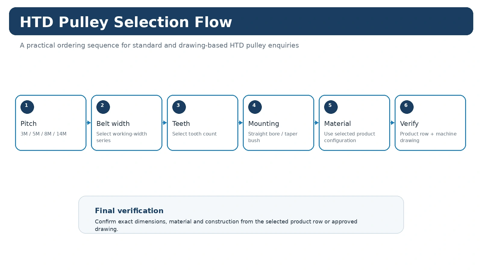
Start with 5 mm HTD family, width code, tooth count and mounting details. Keep the machine requirement separate from the catalogue choice: first identify what the drive must preserve, then compare only the rows or drawings that match that identity. This keeps a familiar-looking pulley from being accepted before its functional interfaces have been checked.
For an existing machine, preserve the original relationship before making changes. For a new design, record the target ratio, operating context and installation envelope so the 5M selection can be reviewed later without relying on memory or a photograph alone.
माप रिकॉर्ड बनाएं
The most useful measurement set contains 5M belt marking, tooth count, width series, bore/bush and hub projection. Mark which values were measured on the machine and which values came from a catalogue or released drawing. When a feature is inaccessible, photograph its relationship to a stable datum and identify it as confirmation-required rather than filling the gap with an assumed value.
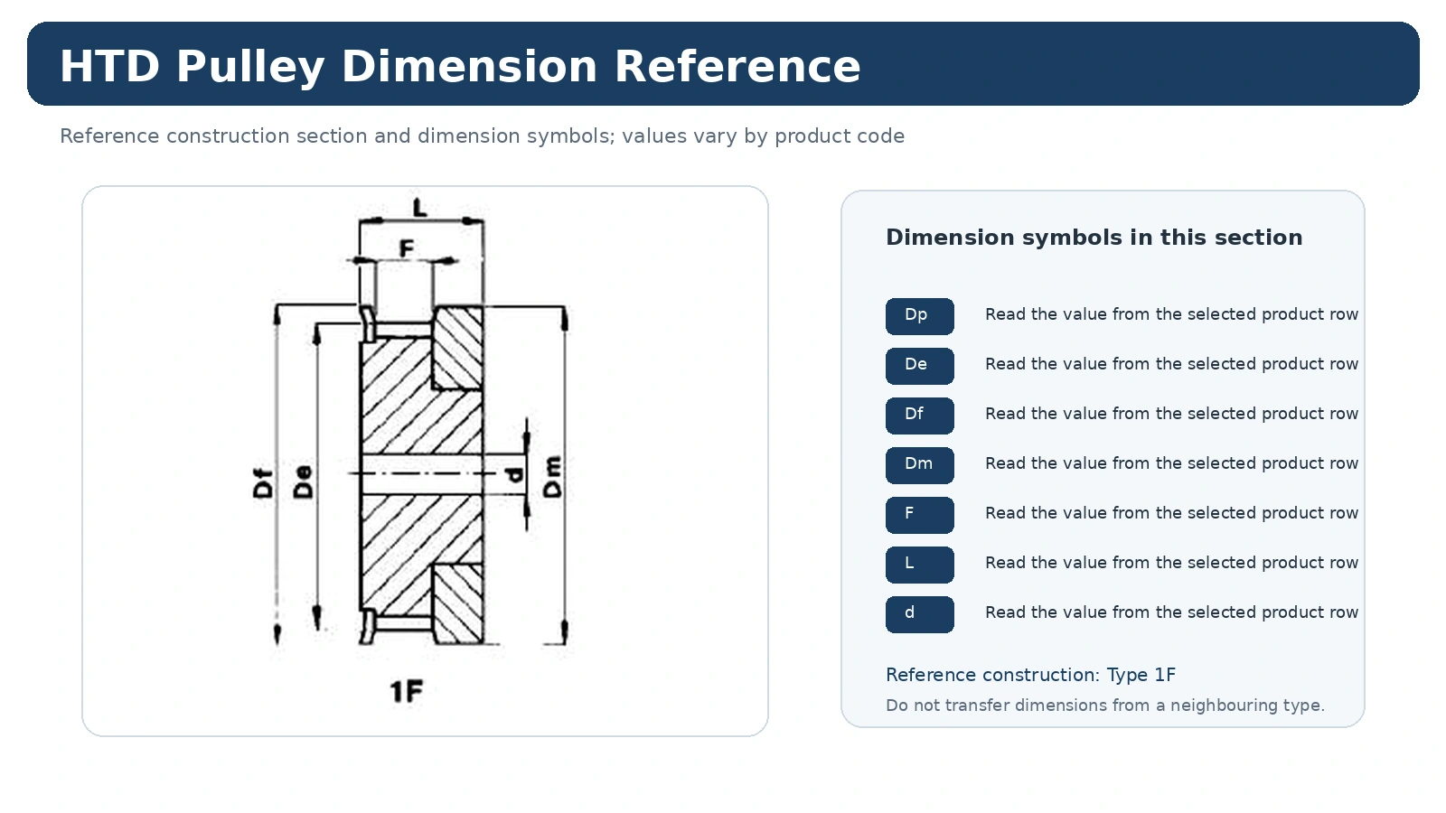
माप संबंधी रेखाचित्रों को पूर्ण पठनीय चौड़ाई में देखा जाना चाहिए। स्क्रीनशॉट को कभी भी स्केल न करें और फिर स्केल किए गए माप को माप के रूप में न मानें; मुद्रित मान और सही निर्माण प्रकार का उपयोग करें।
एक विफलता का तरीका जिससे बचना चाहिए
A common error is using one 5M hub arrangement as if it covered every tooth count. That can produce a part that appears close in the catalogue yet changes ratio, belt line, mounting or service access. Resolve the conflicting feature before requesting price so the quotation refers to one mechanically coherent configuration.
यदि दो संभावित कॉन्फ़िगरेशन शेष रहते हैं, तो मशीन के माप और फ़ोटो तथा पसंदीदा विकल्प दोनों भेजें। इससे कोटेशन में यह स्पष्ट हो जाएगा कि किस इंटरफ़ेस को अभी भी पुष्टि की आवश्यकता है, बजाय इसके कि अनिश्चितता को चुपचाप विनिर्देश में बदल दिया जाए।
तकनीकी विकल्प को कोटेशन के लिए तैयार मद में बदलें
एचटीडी/प्रोफाइल परिवार और बेल्ट की पूरी जानकारी बताएं।
दांतों की संख्या, कार्य चौड़ाई और प्रासंगिक आयाम या ड्राइंग संदर्भ प्रदान करें।
जहां लागू हो, वहां बोर या बुश, शाफ्ट डेटा, हब प्रोजेक्शन और बेल्ट-लाइन की स्थिति को परिभाषित करें।
मात्रा, गंतव्य स्थान, आवश्यक दस्तावेज और अनुरोध के लिए उपयोग किए गए ड्राइंग संशोधन को शामिल करें।
जब ऊपर दिए गए बिंदुओं में से कोई एक बिंदु वास्तव में अज्ञात हो, तो पुष्टि के लिए उसे चिह्नित करें। एक सटीक खुला प्रश्न उस संभावित मान से कहीं अधिक उपयोगी होता है जिसे कभी मापा नहीं गया हो।
खरीदारों द्वारा आमतौर पर पूछे जाने वाले प्रश्न
सबसे पहले किस बात की पुष्टि करनी चाहिए?
Confirm 5 mm HTD family, width code, tooth count and mounting details. That prevents later dimensions from being compared across the wrong product family or installation route.
किसी प्रतिस्थापन के लिए कौन सी जानकारी सबसे उपयोगी होती है?
Send 5M belt marking, tooth count, width series, bore/bush and hub projection, plus clear photographs before the old pulley is removed. The photographs preserve axial orientation and neighboring clearances that a loose part cannot show.
किसी चित्र का उपयोग कब करना चाहिए?
जब भी कैटलॉग पंक्ति शाफ्ट इंटरफ़ेस, हब/फ्लेंज व्यवस्था, फिनिश, टॉलरेंस या मशीन के लिए महत्वपूर्ण निरीक्षण आवश्यकता को पूरी तरह से परिभाषित नहीं करती है, तो नियंत्रित ड्राइंग का उपयोग करें।
Pitch Family Is Only the First Branch of the Selection
5M selection still requires working width, tooth count and mounting geometry. Tooth count changes pitch diameter and can also coincide with changes in body type, hub and material across a catalogue family. The correct comparison therefore stays row-specific after the pitch has been chosen. For a new drive, ratio and center distance must be reviewed together with available diameter and guard clearance.
For a replacement, begin with the mating belt and the installed part. If the belt identity is uncertain, avoid choosing a new family only because the measured pitch appears close. Obtain enough measurements and identification detail to identify the tooth system before comparing product rows.
When to Escalate From a Catalogue Row to a Drawing
Use a drawing-controlled order when the shaft connection, hub position, flange arrangement, material, finish or inspection requirement differs from the normal catalogue configuration. Keep standard HTD tooth geometry explicit on the drawing so the custom machining request does not accidentally obscure the mating-belt requirement.
On mixed-model RFQs, keep every width and tooth count on its own line. A general note such as “same as above” can become unsafe once one model uses a different construction type or bush.
Use the 5M Width Series to Narrow the Catalogue, Not to Replace the Row
The catalogue range separates 5M into 5M-09, 5M-15 and 5M-25 width-series pages. Once the 5M belt family is confirmed, these series give a practical second filter before tooth count and mounting geometry are checked. The series code, however, does not guarantee the same body construction at every diameter.
For replacement work, preserve tooth count, working width, hub projection and flange arrangement together. If the old part has a finished bore or keyway, record the shaft and the feature from a stable datum rather than copying a nominal bore from a previous purchase description. Taper-bush 5M options are a separate mounting path and should be matched by the exact supported series and bush information.
For new designs, combine ratio and center-distance requirements with the available envelope. A model that fits the belt family can still conflict with a guard, bearing housing or service-access requirement if diameter and hub length are considered too late.
Use the Width-Series Pages to Avoid a False Visual Match
Two 5M pulleys can have a similar overall appearance while belonging to different working-width series or construction types. The reliable comparison is therefore the combination of 5M family, width code, tooth count and mounting geometry. If the existing part is already removed, use the belt marking and both-side measurements to reconstruct that combination rather than selecting from photographs alone.
For mixed-model procurement, list each 5M series on its own order line. This prevents a bore, hub or flange note intended for one width series from being copied to another. When one model is custom-machined, identify the controlled drawing revision directly beside that line.
Use 5M Width Series to Organise the Catalogue, Then Select the Exact Row
The 5M family in this project is organised around 5M-09, 5M-15 and 5M-25 straight-bore pages, with selected taper-bush coverage where documented. The width-series code narrows the catalogue, but tooth count and construction type still determine the actual geometry of the pulley that will be supplied.
For replacements, check whether the existing pulley is straight bore or taper bush before comparing rows. A correct 5M pitch and tooth count can still produce a different hub position if the mounting family changes. For new drives, complete belt sizing and ratio selection before using the page tables to choose a model.
Compact 5M width family for matching 5M belt arrangements.
Mid-width 5M family, including documented taper-bush variants.
Wider straight-bore 5M family in the selected catalogue.
Verify construction code, bore/bush and axial envelope on the chosen row.
When a nonstandard shaft interface is required, keep the standard 5M tooth family explicit on the drawing and identify only the features that are being customised. This prevents the custom request from obscuring the belt-side geometry.