HTD-distributierollen voor verwerkingsmachines should be approached as a drive-system decision. The useful starting point is the mating belt and machine interface, followed by tooth count, working width, shaft mounting and duty conditions. This guide explains the checks that help an engineer or buyer turn timing pulley processing machinery into an RFQ that can be verified against a catalogue row or drawing.
Identificeer de drijfveer voordat u dimensies vergelijkt.
For timing pulley processing machinery, identify the complete belt marking before comparing pulley diameters. HTD is a curvilinear synchronous system and the nominal pitch must stay associated with its profile family. Record the driver and driven tooth counts when an existing ratio must be preserved. For a new drive, document the target speed ratio, driver speed and expected load before choosing tooth counts. This prevents a component-level decision from overriding the machine requirement.
Bij een vervangingsproject moet de gemeten waarde worden vergeleken met de geïnstalleerde riem en machineconfiguratie voordat wordt besloten of een catalogusregel equivalent is. Bij een nieuw project moet de ontwerpbasis worden gedocumenteerd, zodat latere onderhoudsteams kunnen begrijpen waarom de steek, het aantal tanden en de montagewijze zijn gekozen.
Afmetingen die de installatie bepalen
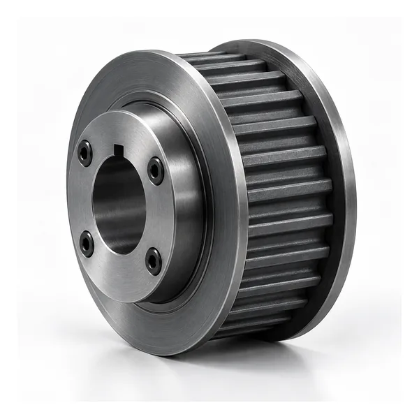
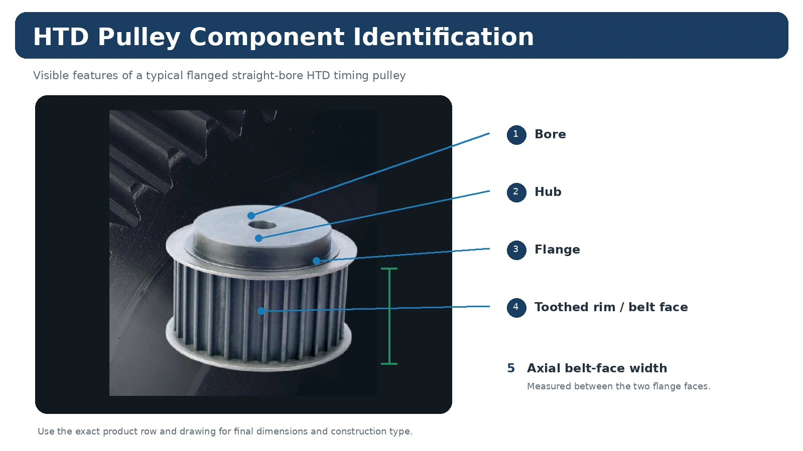
Een poelie kan qua steek en aantal tanden overeenkomen, maar toch niet op de machine passen omdat de boring, naaf, flens of axiale positie verschilt. Meet de asinterface, de breedte van het riemvlak, de naafuitsteeksel aan beide zijden en de riemlijn ten opzichte van een stabiel referentiepunt op de machine. Als een conische bus wordt gebruikt, noteer dan zowel de poelieserie als de buscode. Indien een afgewerkte boring vereist is, vermeld dan de passing, de spiebaan en eventuele bevestigingsmethode op de tekening.
Bij een vervangingsproject moet de gemeten waarde worden vergeleken met de geïnstalleerde riem en machineconfiguratie voordat wordt besloten of een catalogusregel equivalent is. Bij een nieuw project moet de ontwerpbasis worden gedocumenteerd, zodat latere onderhoudsteams kunnen begrijpen waarom de steek, het aantal tanden en de montagewijze zijn gekozen.
Bedrijfsomstandigheden die bij de selectie horen
The same nominal timing pulley processing machinery component can see very different service depending on the machine. Starts per hour, reversing, shock loading, continuous operating time, temperature, contamination, cleaning and access for tensioning all influence the drive. A compact automation axis emphasizes repeatable motion and controlled alignment, while a conveyor or process machine may emphasize continuous duty and service access. Supply these conditions instead of asking the pulley to be selected from size alone.
Bij een vervangingsproject moet de gemeten waarde worden vergeleken met de geïnstalleerde riem en machineconfiguratie voordat wordt besloten of een catalogusregel equivalent is. Bij een nieuw project moet de ontwerpbasis worden gedocumenteerd, zodat latere onderhoudsteams kunnen begrijpen waarom de steek, het aantal tanden en de montagewijze zijn gekozen.
Controlepunten vóór installatie
De inspectie moet zich richten op afmetingen die van invloed zijn op de aandrijving: de asinterface, axiale positie, tandconditie, tandbreedte en eventuele door de tekening bepaalde slingering of referentiepuntrelatie. Een algemene kwaliteitsverklaring is geen garantie voor acceptatie. Indien een dimensionaal rapport, materiaaldocument of orderspecifiek document vereist is, dient u dit vóór de productie aan te geven. Let tijdens het onderhoud op beschadiging van de flens, slijtage van de randen, vuil en tekenen dat de poelie op de as is verschoven.
Bij een vervangingsproject moet de gemeten waarde worden vergeleken met de geïnstalleerde riem en machineconfiguratie voordat wordt besloten of een catalogusregel equivalent is. Bij een nieuw project moet de ontwerpbasis worden gedocumenteerd, zodat latere onderhoudsteams kunnen begrijpen waarom de steek, het aantal tanden en de montagewijze zijn gekozen.
Openstaande vragen die u moet beantwoorden voordat u bestelt.
Welk exact HTD-profiel en welke breedte is geïnstalleerd of gespecificeerd?
Welke verhouding of welk bestaand aantal tanden moet behouden blijven?
Welke boring, passing, spiebaan of conische busconstructie is vereist?
Hoeveel ruimte is er beschikbaar voor de naafuitsteeksels en flens?
Wat zijn de snelheid, belasting, starts, achteruitrijfunctie en bedrijfsuren?
Welke tekeningen, materiaal- of inspectierapporten moeten bij de levering worden gevoegd?
Wat u met de offerteaanvraag moet meesturen
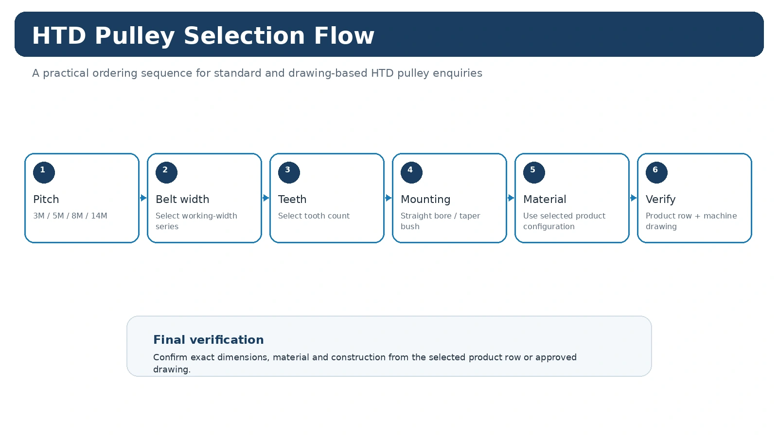
Stuur het profiel, het aantal tanden, de riembreedte, de asinterface, de naaf-/flensdetails, de hoeveelheid, de bestemming en een tekening of een schets van de vervangingsafmetingen. Voeg voor een nieuwe aandrijving de snelheid, de overbrengingsverhouding, de belasting, de hartafstand en de omgeving toe. Controleer de HTD-productfamilies, gebruik de selectiegids, of vergelijk de relevante toepassingsnotities.
Processing Equipment Varies Widely
Mixers, feeders, handling machines and other processing equipment can impose very different start-stop and environmental conditions. Give the actual machine function and duty rather than selecting from the phrase “processing machinery” alone.
Capture operating hours, starts and stops, reversal if present, nearby guards and the condition of the shaft support. These details provide the application context for the pulley without turning the page into an unsupported power or life-rating claim.
Use the RFQ to Separate Standard Geometry From Project Requirements
If the pulley needs a special material, finish, inspection record or custom shaft feature, list that change independently from the standard HTD family so the quotation remains clear.
Het aankoopbewijs moet een duidelijke koppeling bewaren tussen de machinevereisten en de geselecteerde poelie. Dat betekent dat de volledige riem- of profielidentificatie, het aantal tanden, de werkbreedte en de asinterface-informatie samen met de productcode moeten worden vermeld. Eventuele speciale materiaal-, afwerkings-, tolerantie-, markerings- of rapportagevereisten moeten afzonderlijk worden vermeld, zodat ze niet kunnen worden aangezien voor een universeel kenmerk van de hele productfamilie.
Inkoop en documentatie
Zodra de selectie duidelijk is, dient u de geaccepteerde productidentiteit, hoeveelheid, bestemming en tekeningrevisie op dezelfde inkoopregel te bewaren. Standaard catalogusonderdelen worden doorgaans gepland op basis van minimale productieaantallen, terwijl grotere of duurdere artikelen kunnen worden beoordeeld op basis van de daadwerkelijke orderwaarde. Gekwalificeerde monsters van 1 tot 5 stuks voor nieuwe klanten kunnen tegen monsterprijs worden beoordeeld, mits de configuratie en het productieproces geschikt zijn.
Bestellingen van verschillende modellen kunnen worden samengevoegd tot een orderwaarde van ongeveer USD 1.500. Speciale materialen en processen volgen de minimale afnamehoeveelheid die voor dat proces vereist is. Zeer kleine bestellingen van één of twee stuks worden alleen behandeld als gekwalificeerde technische validatie of betaalde proefbestellingen, en niet als vervangingsbestellingen voor de detailhandel.
De levertijd wordt vastgesteld nadat de technische specificaties duidelijk zijn. Standaardonderdelen hebben doorgaans een levertijd van 10-25 werkdagen, maatwerkcomponenten 20-45 werkdagen en projectgebaseerde assemblages of bijbehorende apparatuur 45-120 werkdagen, indien van toepassing. EXW, FOB, CIF en DAP worden veelvuldig ondersteund; FCA, CFR, CPT, CIP en DDP kunnen worden besproken voor geschikte verzendmethoden. Beschouw deze levertijden als planningstermijnen, niet als een leveringsbelofte vóór de orderbeoordeling.
Een praktische beslissingsreeks
Start with process sequence, load cycle, cleanliness and drive envelope. Keep the machine requirement separate from the catalogue choice: first identify what the drive must preserve, then compare only the rows or drawings that match that identity. This keeps a familiar-looking pulley from being accepted before its functional interfaces have been checked.
For an existing machine, preserve the original relationship before making changes. For a new design, record the target ratio, operating context and installation envelope so the processing-drive definition can be reviewed later without relying on memory or a photograph alone.
Stel een meetregistratie op.
The most useful measurement set contains speed ratio, load cycle, pitch family, width, shaft interface and environment. Mark which values were measured on the machine and which values came from a catalogue or released drawing. When a feature is inaccessible, photograph its relationship to a stable datum and identify it as confirmation-required rather than filling the gap with an assumed value.
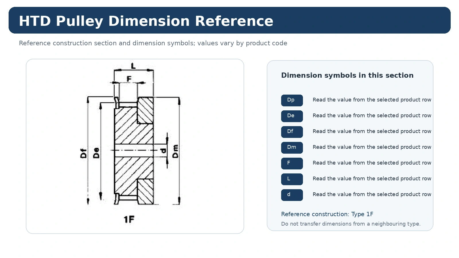
Maattekeningen moeten op volledige, leesbare breedte worden bekeken. Schaal nooit een schermafbeelding en gebruik de geschaalde afmeting vervolgens als maat; gebruik de afgedrukte waarde en het juiste constructietype.
Een storing die je beter kunt vermijden
A common error is assuming an application label alone determines pulley size. That can produce a part that appears close in the catalogue yet changes ratio, belt line, mounting or service access. Resolve the conflicting feature before requesting price so the quotation refers to one mechanically coherent configuration.
Als er nog twee mogelijke configuraties overblijven, stuur dan zowel de machineafmetingen en foto's als de voorkeursoptie. De offerte kan dan aangeven welke interface nog bevestiging nodig heeft, in plaats van onzekerheid stilzwijgend in een specificatie te verwerken.
Zet de technische keuze om in een offerteklaar item.
Vermeld de HTD/profielfamilie en volledige rieminformatie.
Vermeld het aantal tanden, de werkbreedte en de relevante afmetingen of tekeningreferenties.
Definieer de boring of bus, asgegevens, naafuitsteeksel en riemlijnpositie waar van toepassing.
Voeg de hoeveelheid, bestemming, benodigde documenten en de gebruikte tekeningrevisie toe aan de aanvraag.
Als een van de bovenstaande items echt onbekend is, geef dit dan aan ter bevestiging. Een precieze, open vraag is nuttiger dan een plausibele waarde die nooit is gemeten.
Veelgestelde vragen van kopers
Wat moet er als eerste bevestigd worden?
Confirm process sequence, load cycle, cleanliness and drive envelope. That prevents later dimensions from being compared across the wrong product family or installation route.
Welke informatie is het meest nuttig voor een vervanging?
Send speed ratio, load cycle, pitch family, width, shaft interface and environment, plus clear photographs before the old pulley is removed. The photographs preserve axial orientation and neighboring clearances that a loose part cannot show.
Wanneer moet een tekening worden gebruikt?
Gebruik een gecontroleerde tekening wanneer de catalogusregel de asinterface, de naaf-/flensconfiguratie, de afwerking, de tolerantie of de inspectie-eisen die voor de machine relevant zijn, niet volledig definieert.
Machine Conditions to Record for Processing Machinery
Do not select a pulley from the industry name alone. Record the operating pattern of the actual machine: driver and driven speeds or ratio, torque or power where available, center distance, hours per day, start/stop frequency, reversal, contamination and the available guard/shaft envelope. These details explain the duty without turning a general article into an unsupported product rating.
For maintenance replacement, add the installed belt marking, tooth count, working face, hub projection and shaft interface. If there has been edge wear or tracking trouble, capture the belt line and bearing/shaft condition before altering pulley geometry.
Installation Planning for Processing Machinery
Confirm that the selected pulley can be fitted and removed with the available service access. A hub that is technically compatible can still cause downtime if adjacent bearings or guards block installation. Maintain the intended belt plane and review flange clearance so the belt is guided without using persistent flange contact as a substitute for alignment.
Where washdown, dust, fibers, chips or process residue are present, include the environment in the RFQ. Material and maintenance decisions should be reviewed against the actual configuration and environment rather than copied from another application.
Processing Equipment Should Be Described by Its Local Drive Conditions, Not the Industry Label
“Processing machinery” covers many very different machines, so it is especially important to define the individual timing drive. Record the driven function, speed relationship, duty, center distance, shaft arrangement and environmental conditions at that location. The correct HTD family cannot be selected reliably from the industry label alone.
For replacements, inspect the belt, flange and shaft position before disassembly. If washdown, dust, product residue, heat or chemical exposure is relevant, identify the actual condition and the requested material or documentation rather than assuming one specification for the whole plant. Keep the belt marking and pulley measurements in the same record.
For new designs, treat the published catalogue geometry as the component definition and the machine data as the project definition. Where the two meet—shaft, hub, belt line and available envelope—is where the RFQ needs the most detail.
Separate Process Environment Requirements From Basic Pulley Identification
When heat, washdown, abrasive residue or chemical exposure matters, add it after the pulley has been identified from pitch, width, tooth count and mounting geometry. This order avoids letting an environmental requirement obscure the fundamental belt-side match. It also makes quotation clearer: the supplier can distinguish the standard component geometry from any requested material, finish or documentation needed for the process zone.
For replacement investigations, record whether the old component shows corrosion, product buildup, flange wear or fretting at the shaft interface. Those observations may influence the project discussion, but they should be kept separate from measured dimensions so damage is not copied into the new part.
Use Process Conditions to Complete the Pulley Specification
Processing machinery covers a wide range of mixers, feeders, cutters, pumps and production equipment. The pulley can be selected only after the drive function is clear: belt family, ratio, center distance, working width and shaft connection come first, followed by the environmental and maintenance constraints that matter to the actual process.
Do not assume that every processing application needs the same material or finish. Cleaning chemicals, food-contact boundaries, dust, heat or corrosion concerns should be stated when they genuinely apply. Those requirements may change the feasible manufacturing route and order quantity, so they belong in the RFQ before production is planned.
Identify what the timing drive powers and whether the motion is continuous or cyclic.
Provide belt family, teeth, width, center distance or installed geometry.
State temperature, contamination, cleaning or corrosion constraints where relevant.
Check guard removal, shaft access and space for the selected mounting method.
For replacements, preserve the original belt line and ratio unless the process engineer has approved a change. A clear machine-side description prevents a component substitution from unintentionally changing process speed or maintenance access.