Panduan Pemilihan Pulley Timing HTDPilih jarak antar gigi, jumlah gigi, lebar sabuk, antarmuka poros, dan konstruksi secara berurutan dan terkontrol.
Apa yang Dikendalikan oleh Keputusan Ini
Pilih jarak antar gigi, jumlah gigi, lebar sabuk, antarmuka poros, dan konstruksi secara berurutan dan terkontrol. Keputusan tersebut harus didokumentasikan dengan penunjukan sabuk, kode produk, atau gambar karena puli penggerak merupakan bagian dari sistem penggerak. Pencocokan visual tidak membuktikan kompatibilitas gigi atau kesesuaian poros.
Alur Kerja yang Direkomendasikan
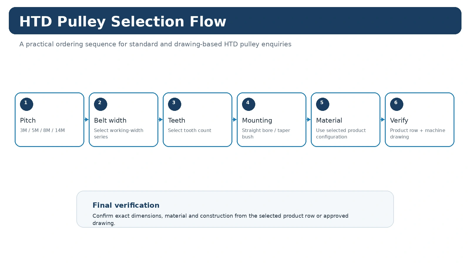
Mulailah dengan sabuk penghubung dan persyaratan penggerak. Konfirmasikan jarak antar gigi/profil, jumlah gigi, dan lebar kerja. Kemudian periksa antarmuka poros, hub dan selubung flensa, material, dan persyaratan inspeksi terkontrol apa pun. Untuk penggantian, ukur bagian lama dari kedua sisi dan catat garis sabuk relatif terhadap datum mesin yang stabil.
Kesalahan Umum yang Harus Dihindari
- Memilih berdasarkan diameter luar sambil mengabaikan sistem gigi.
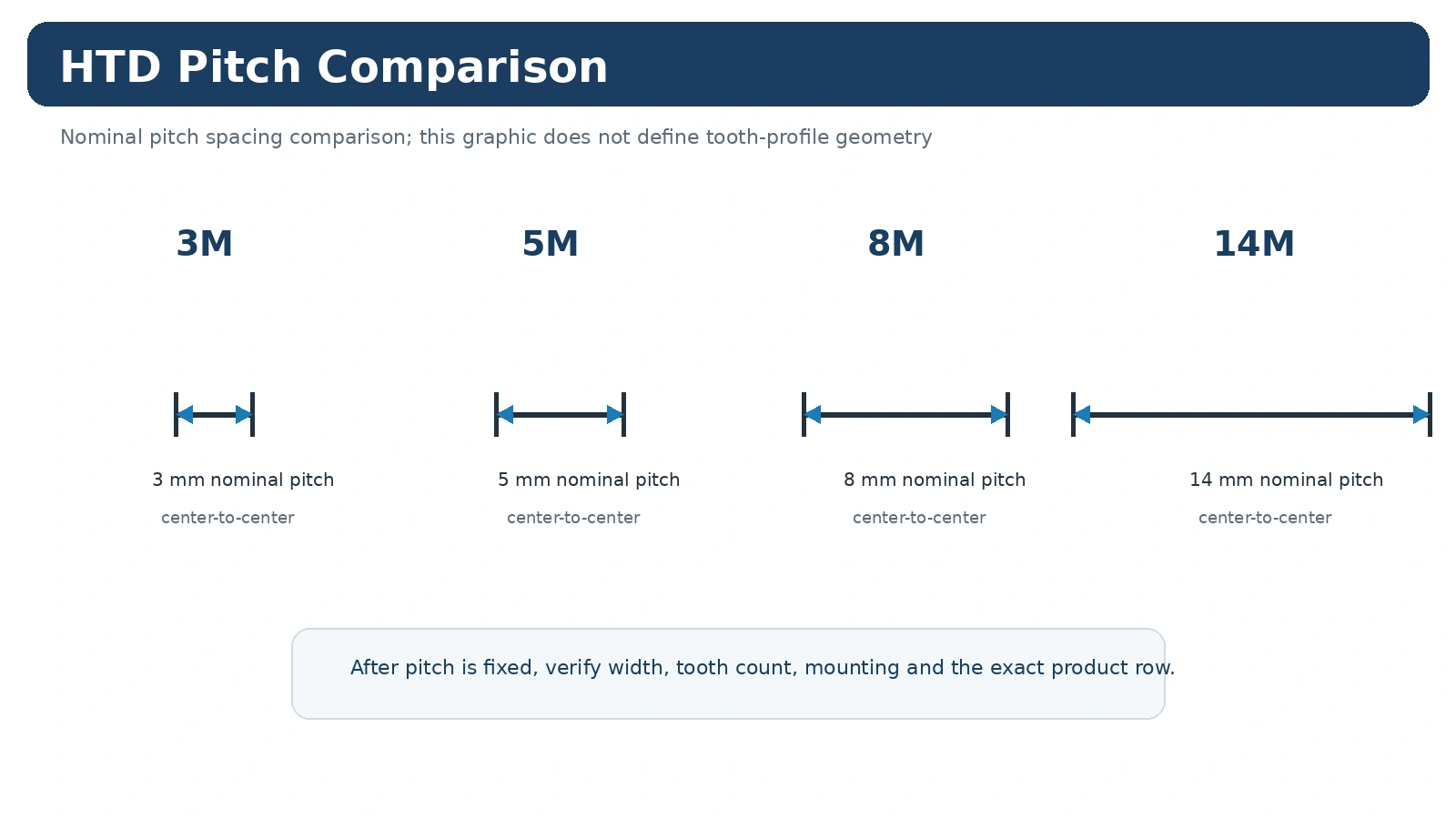
- Dengan asumsi bahwa setiap profil lengkung dengan jarak nominal yang sama dapat saling menggantikan.
- Hanya mengukur satu sisi dan mengabaikan proyeksi hub atau garis sabuk yang bergeser.
- Persyaratan seperti kesesuaian lubang, alur pasak, kode bushing, atau inspeksi akan ditunda hingga setelah penawaran harga.
- Menggunakan nilai tegangan atau toleransi sabuk universal tanpa dasar desain mesin dan sabuk.
Gunakan Panduan ini dalam Permintaan Penawaran (RFQ)
Setelah variabel-variabel kunci tercatat, buka Keluarga produk HTD, bandingkan yang relevan konteks aplikasiatau kirimkan gambar dan detail pesanan melalui formulir di bawah ini.
Gunakan Seleksi Dua Tahap: Sisi Sabuk Terlebih Dahulu, Antarmuka Mesin Kedua
Pertama, tentukan keluarga HTD, seri lebar, dan jumlah gigi. Kemudian tinjau jalur pemasangan, ukuran hub/flange, ketersediaan material, dan jarak bebas mesin menggunakan baris produk tertentu.
Untuk drive baru, berikan hubungan kecepatan, jarak pusat, dan beban kerja. Untuk penggantian, berikan ukuran terpasang dan foto. Hal ini menjaga agar panduan tetap bermanfaat tanpa menggantikan saran umum untuk baris katalog atau gambar proyek.
Pilihan yang Andal Beralih dari Sabuk Konveyor ke Antarmuka Mesin
Konfirmasikan keluarga HTD, pilih lebar kerja dan jumlah gigi, tinjau konstruksi lubang lurus atau bushing tirus, lalu verifikasi hub, flensa, material, dan area pemasangan. Akhiri dengan baris katalog atau gambar yang telah dirilis.
Ketika keputusan melibatkan mesin yang sudah ada, pisahkan pengukuran, nilai katalog, dan persyaratan proyek baru. Hal ini mencegah pengukuran lapangan diperlakukan secara diam-diam sebagai dimensi nominal atau perubahan yang diinginkan disalahartikan sebagai fitur standar keluarga mesin.
Gunakan Gambar dan Tabel Bersama-sama
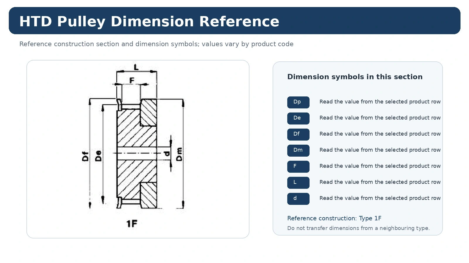
Gambar konstruksi menjelaskan simbol dan hubungannya. Tabel khusus baris memberikan nilai aktual untuk model yang dipilih. Jangan mengubah skala ilustrasi atau mentransfer dimensi dari lebar atau jumlah gigi lain hanya karena produknya terlihat serupa.
Jika katalog tidak mengatur persyaratan kesesuaian, kelurusan, toleransi, penyelesaian akhir, atau dokumen tertentu, cantumkan persyaratan tersebut pada gambar proyek atau RFQ dan jadikan bagian dari tinjauan pesanan.
Daftar Periksa Rilis
Pertahankan identitas sabuk/profil, lebar kerja, jumlah gigi, definisi pemasangan, kuantitas, dan revisi gambar pada baris pesanan teknis yang sama. Tambahkan beban mesin untuk penggerak baru atau foto dan pengukuran yang jelas untuk pekerjaan penggantian. Ini memberikan konfigurasi kepada bagian pembelian yang dapat diperiksa, bukan sekumpulan dimensi yang terpisah.
Apa yang Tidak Digantikan oleh Panduan Ini
Panduan ini membantu mengatur proses pemilihan dan pengukuran; panduan ini tidak menggantikan baris produk, data sabuk, atau gambar proyek yang tepat. Jika daya, torsi, kecepatan, kesesuaian, toleransi, atau batas layanan yang dibutuhkan tidak tercantum dalam tabel katalog atau gambar yang disetujui, simpan sebagai masukan desain atau RFQ dan verifikasi untuk penggerak yang sebenarnya.
Batasan tersebut berguna selama proses pengadaan karena mencegah penjelasan teknik umum dikutip kemudian seolah-olah itu adalah nilai yang dijamin untuk setiap konfigurasi puli HTD.
Terapkan Pemilihan Pulley Htd pada Mesin Nyata
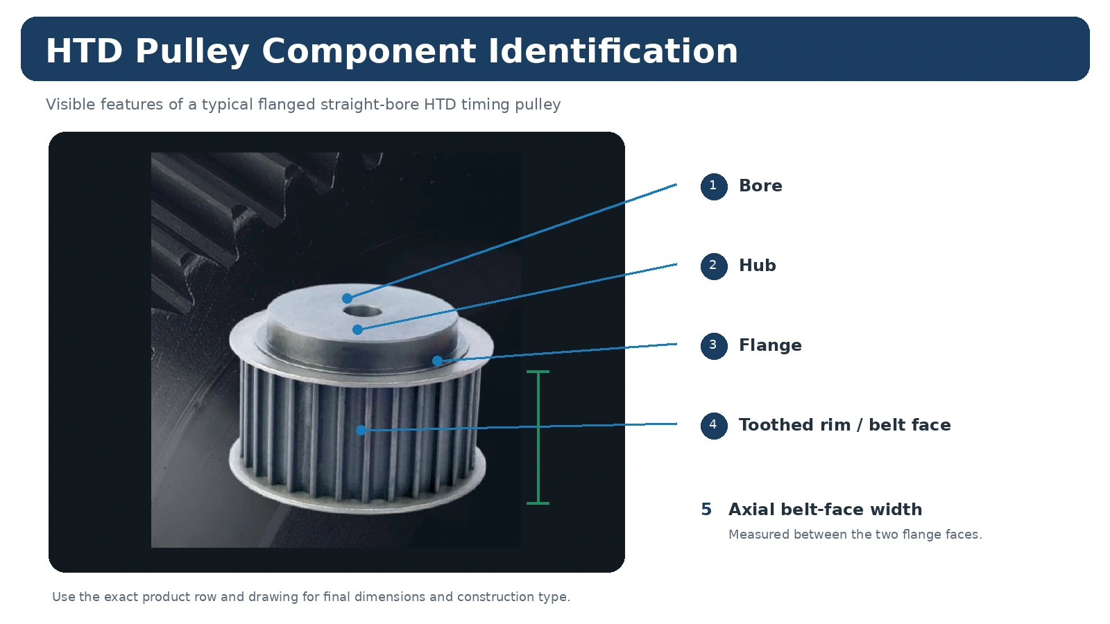
Kumpulkan profil/pitch, lebar sabuk, jumlah gigi, antarmuka poros, dan beban mesin. Gunakan katalog atau gambar dimensi untuk memberi nama fitur secara konsisten, lalu pisahkan nilai mesin yang diukur dari nilai katalog. Aturan kerjanya sederhana: pertahankan geometri sisi sabuk dan geometri sisi poros sebagai dua pemeriksaan terpisah sampai satu baris katalog atau gambar memenuhi keduanya. Jika komponen lama aus atau dimodifikasi, perlakukan pengukurannya sebagai data lapangan daripada menganggapnya sebagai dimensi nominal asli.
Untuk pekerjaan penggantian, bandingkan hubungan hub depan dan belakang dan catat sisi mana yang membentuk garis sabuk. Untuk desain baru, catat hubungan kecepatan, jarak pusat, beban kerja, dan area pemasangan sebelum kode produk dipilih. Hal ini menjaga agar pemilihan tetap dapat dilacak ketika penggerak diservis di kemudian hari.
Gunakan gambar untuk menutup celah yang tersisa.
Baris produk standar dapat menentukan keluarga pitch, jumlah gigi, dan banyak dimensi amplop, tetapi kecocokan poros spesifik proyek, detail kunci, perubahan hub, penyelesaian, atau batasan inspeksi mungkin masih memerlukan gambar. Tunjukkan datum mesin dan dimensi yang benar-benar mengontrol perakitan daripada mengisi gambar dengan dimensi referensi yang tidak terkontrol.
Jika terdapat dua konfigurasi katalog yang tampak memungkinkan, identifikasi apa yang masih belum diketahui dan ukur fitur tersebut secara langsung. Ini lebih dapat diandalkan daripada memilih konfigurasi dengan diameter luar yang paling mendekati atau foto yang paling familiar.
Data Rilis untuk Pemilihan Pulley HTD
Pertahankan identitas produk lengkap dengan detail pembelian: keluarga HTD, seri lebar, jumlah gigi, lubang atau bushing, kuantitas, dan revisi gambar jika digunakan. Tambahkan persyaratan material, finishing, inspeksi, atau dokumentasi khusus pesanan secara terpisah. Hal ini mempermudah pekerjaan penggantian di kemudian hari karena konfigurasi yang diterima dapat dipulihkan tanpa perlu merekonstruksi keputusan dari riwayat email.
Ubah Pilihan Menjadi Spesifikasi yang Siap untuk Penawaran Harga
Permintaan puli HTD yang siap untuk penawaran harga harus mencantumkan sabuk/profil, jumlah gigi, lebar kerja, antarmuka poros atau bushing tirus, kuantitas, dan tujuan. Tambahkan informasi kecepatan, rasio, jarak pusat, dan beban kerja jika puli tersebut untuk penggerak baru, bukan penggantian yang sama persis. Untuk penggantian, sertakan pengukuran dari kedua sisi dan gambar yang jelas dari tanda sabuk yang terpasang. Dengan menyatukan input ini, baris produk, tampilan konstruksi, dan persyaratan pemesinan khusus apa pun dapat ditinjau sebagai satu spesifikasi yang terkontrol.