Timing Pulley Tooth Count and Drive Ratio: Relate driver and driven tooth counts to speed ratio while keeping minimum-size and duty checks separate.
What This Decision Controls
Relate driver and driven tooth counts to speed ratio while keeping minimum-size and duty checks separate. The decision should be documented with the belt designation, product code or drawing because a timing pulley is part of a drive system. A visual match does not prove tooth compatibility or shaft fit.
Recommended Workflow
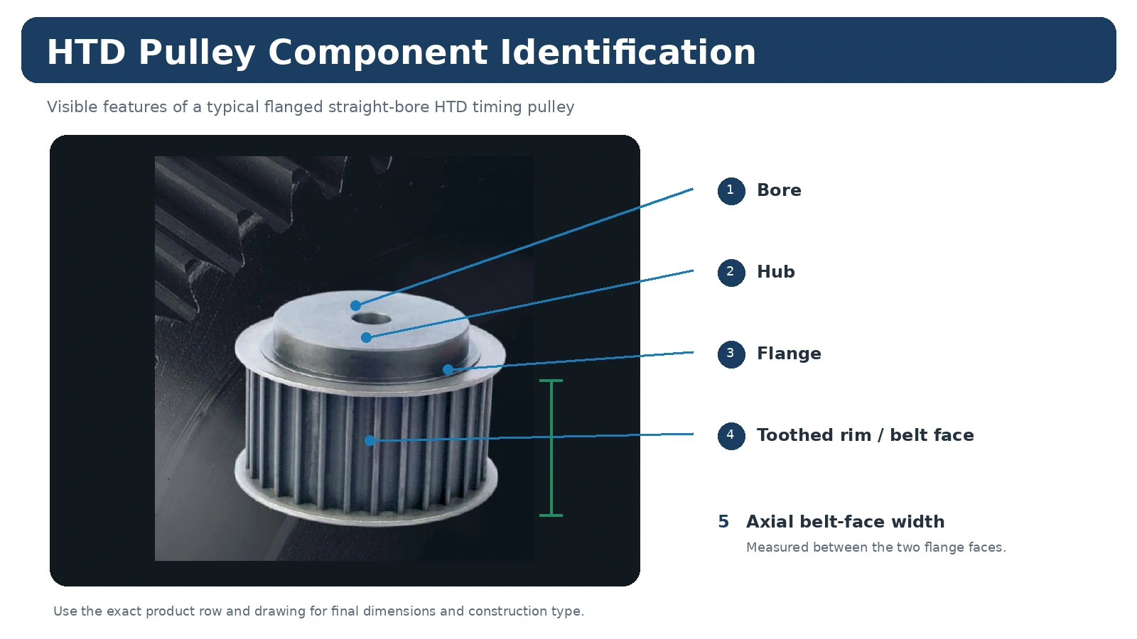
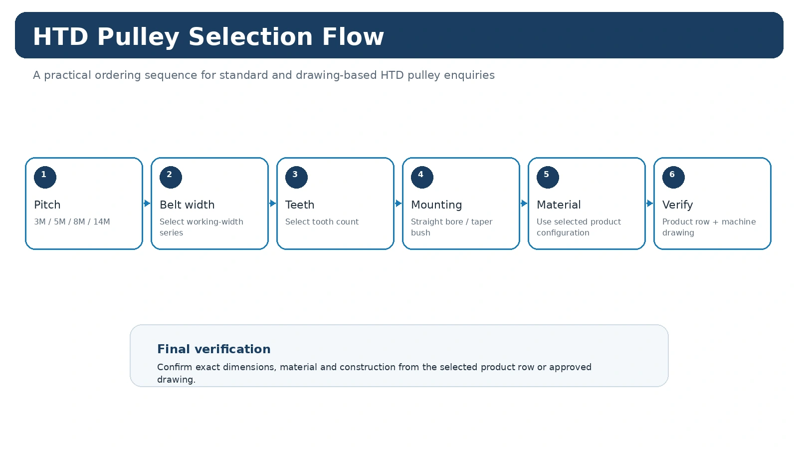
Start with the mating belt and drive requirement. Confirm pitch/profile, tooth count and working width. Then check the shaft interface, hub and flange envelope, material and any controlled inspection requirement. For a replacement, measure the old part from both sides and record the belt line relative to a stable machine datum.
Common Errors to Avoid
- Choosing by outside diameter while ignoring the tooth system.
- Assuming that every curvilinear profile with the same nominal pitch is interchangeable.
- Measuring only one side and missing hub projection or an offset belt line.
- Leaving bore fit, keyway, bush code or inspection requirements until after quotation.
- Using a universal belt-tension or tolerance value without the machine and belt design basis.
Use the Guide in an RFQ
Once the key variables are captured, open the HTD product families, compare the relevant application context, or send the drawing and order details through the form below.
Tooth Count Affects Both Ratio and Envelope
The tooth-count pair participates in the speed relationship and also changes pulley diameter. Check both consequences before accepting a new count for a drive.
For replacement work, count the existing teeth when markings are unclear and preserve center distance and belt identity. For new designs, confirm the resulting diameters fit the available guard and shaft envelope.
Tooth Count Changes Both Ratio and Physical Envelope
For a two-pulley synchronous drive, the tooth-count relationship determines speed ratio. After the ratio is chosen, confirm pulley diameters, belt engagement, center distance, guard clearance and the hub/shaft interface before release.
When the decision involves an existing machine, keep measurements, catalogue values and new project requirements separate. This prevents a field measurement from being silently treated as a nominal dimension or a desired change from being mistaken for a standard family feature.
Use the Drawing and Table Together
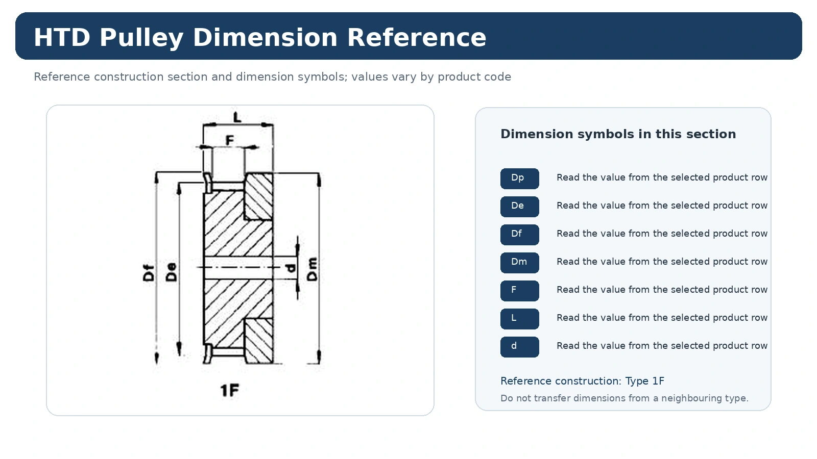
Construction drawings explain the symbols and relationships. The row-specific table provides the actual values for the selected model. Do not scale the illustration or transfer dimensions from another width or tooth count simply because the product looks similar.
Where the catalogue does not control a required fit, runout, tolerance, finish or document, put that requirement on the project drawing or RFQ and make it part of the order review.
Release Checklist
Keep the belt/profile identity, working width, tooth count, mounting definition, quantity and drawing revision on the same technical order line. Add machine duty for a new drive or clear photographs and measurements for replacement work. This gives purchasing a configuration that can be checked instead of a collection of disconnected dimensions.
What This Guide Does Not Replace
This guide helps organize the selection and measurement process; it does not replace the exact product row, belt data or project drawing. If a required power, torque, speed, fit, tolerance or service limit is not stated in the relevant catalogue table or approved drawing, keep it as a design or RFQ input and verify it for the actual drive.
That boundary is useful during procurement because it prevents a general engineering explanation from being quoted later as if it were a guaranteed value for every HTD pulley configuration.
Apply the Tooth Count And Drive Ratio to a Real Machine
Collect driver and driven tooth counts, shaft speeds, center distance and allowable pulley envelope. Use the catalogue or dimension drawing to name features consistently, then separate measured machine values from catalogue values. The working rule is simple: changing tooth count changes ratio and pitch diameter together; it is not a cosmetic substitution. If the old component is worn or modified, treat its measurements as field data rather than assuming they are the original nominal dimensions.
For replacement work, compare both front and rear hub relationships and note which face establishes the belt line. For a new design, record the speed relationship, center distance, duty and installation envelope before the product code is selected. This keeps the selection traceable when the drive is serviced later.
Use the Drawing to Close Remaining Gaps
A standard product row can define pitch family, tooth count and many envelope dimensions, but project-specific shaft fits, key details, hub changes, finishes or inspection limits may still require a drawing. Show the machine datum and the dimensions that actually control assembly rather than filling the drawing with uncontrolled reference dimensions.
If two catalogue configurations appear possible, identify what is still unknown and measure that feature directly. This is more reliable than choosing the configuration with the closest outside diameter or the most familiar photograph.
Release Data for Tooth Count And Drive Ratio
Keep the complete product identity with the purchase line: HTD family, width series, tooth count, bore or bush, quantity and the drawing revision where one is used. Add order-specific material, finish, inspection or documentation requirements separately. This makes later replacement work easier because the accepted configuration can be recovered without reconstructing the decision from email history.
Confirm Ratio and Physical Envelope Together
Tooth count sets the pitch diameter relationship and therefore affects speed ratio, outside envelope and belt wrap at the same time. Check the driver/driven tooth-count pair against the intended ratio, then verify center distance, available pulley diameter, belt width and shaft-interface space before releasing the part. Avoid treating a ratio calculation as a complete pulley selection: the same ratio can often be achieved with more than one tooth-count pair, and the machine envelope or minimum practical pulley size may decide between them.