Application context helps define duty cycle, access, environment, guarding and service requirements around an HTD pulley. It does not replace model-level technical data or the machine designer’s drive calculation.
Six Practical Machine Contexts
Open a context to see which operating details should accompany a pulley RFQ.
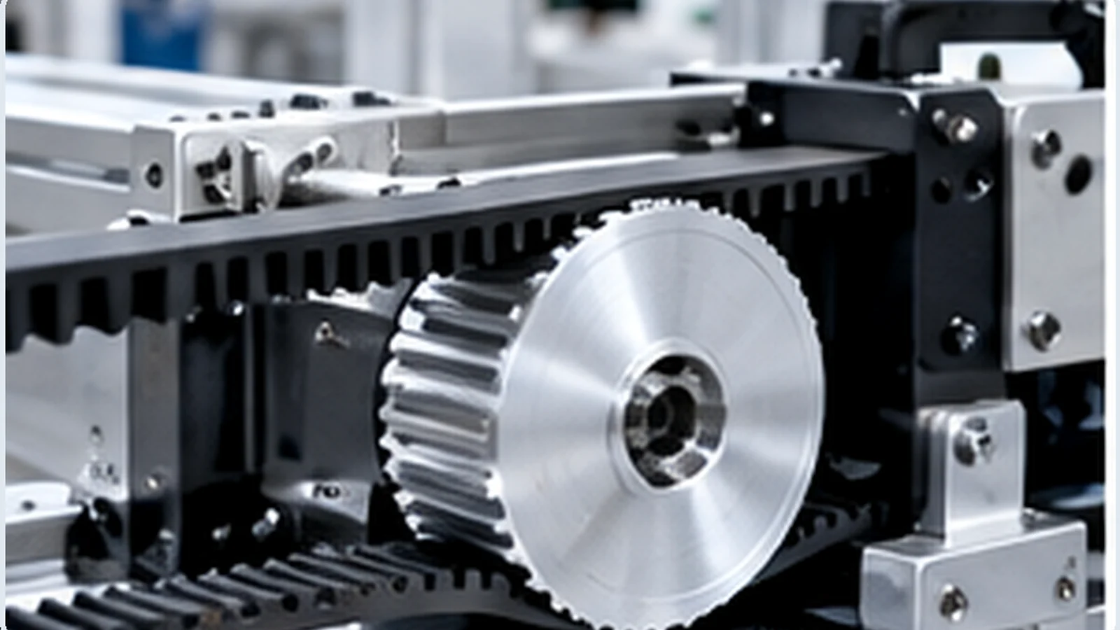 Industrial Automation
 Packaging Machinery
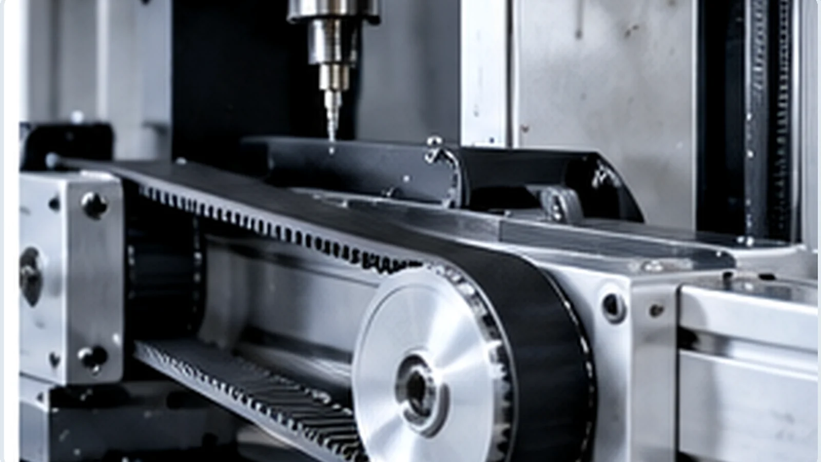 Machine Tools
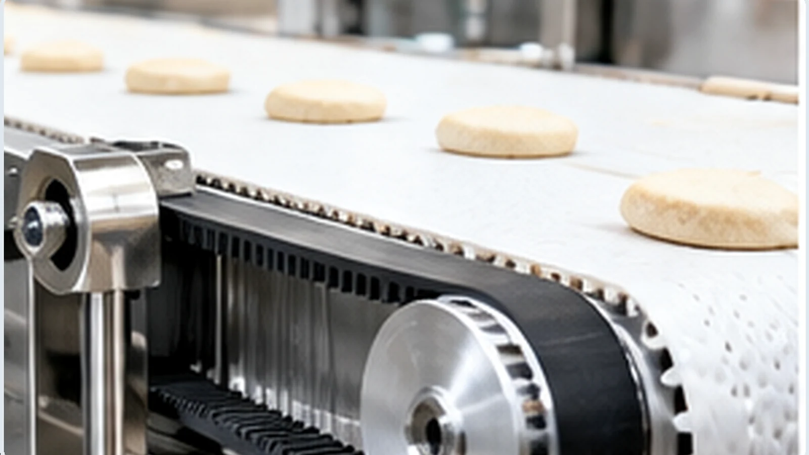
 Conveying Equipment
 Textile & Paper Machinery
 Processing Machinery
Capture the Installed Drive Before Disassembly
Photograph the belt line, pulley faces, shaft end, guard clearance and adjacent bearings while the drive is still assembled. Record the belt marking and tooth count, then measure the hub and shaft interface from both sides. This preserves information that may be difficult to reconstruct from a loose pulley on a bench.
If a measured value conflicts with an old purchase record, send both. A technical review can resolve the discrepancy without forcing one uncertain value into the enquiry.
Start From Speed Relationship, Load and Installation Envelope
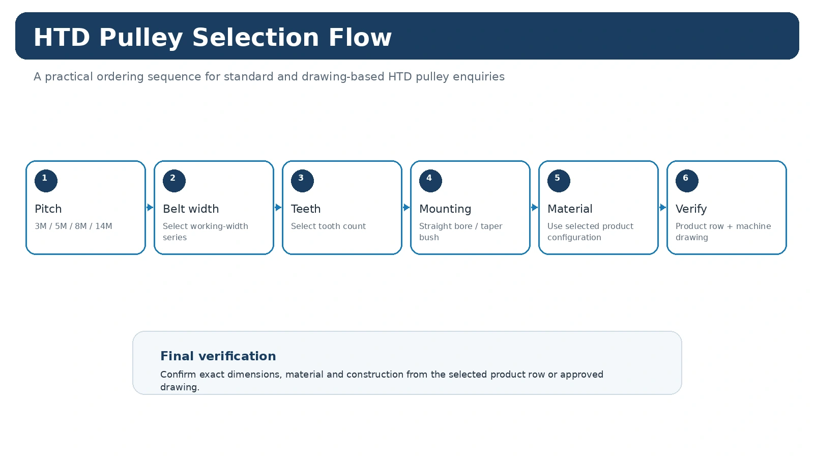
For a new machine, provide driver speed, driven speed or target ratio, power or torque, center distance, duty cycle and expected operating environment. Add shaft dimensions, available axial space and service-access constraints. Those inputs help determine whether a catalogue family is suitable or whether the project requires a drawing-controlled configuration.
Application Pages Translate Machine Conditions Into Pulley Inputs
Application context matters because the same HTD pitch can appear in machines with very different operating patterns. An automation axis may prioritize indexing and a compact envelope; a conveyor may place more emphasis on duty cycle, contamination and service access; a machine-tool auxiliary drive can be sensitive to belt-line alignment and the location of a replacement hub. The application pages therefore do not prescribe a universal pulley size. They show which machine information should accompany the technical selection.
For a new drive, record driver and driven speeds or the required ratio, transmitted power or torque, center distance, operating hours, starts and stops, environment and the available shaft/guard envelope. For replacement work, first capture the installed belt marking and pulley geometry. That preserves the original system identity before changes are considered.
Common Integration Checks Across Machines
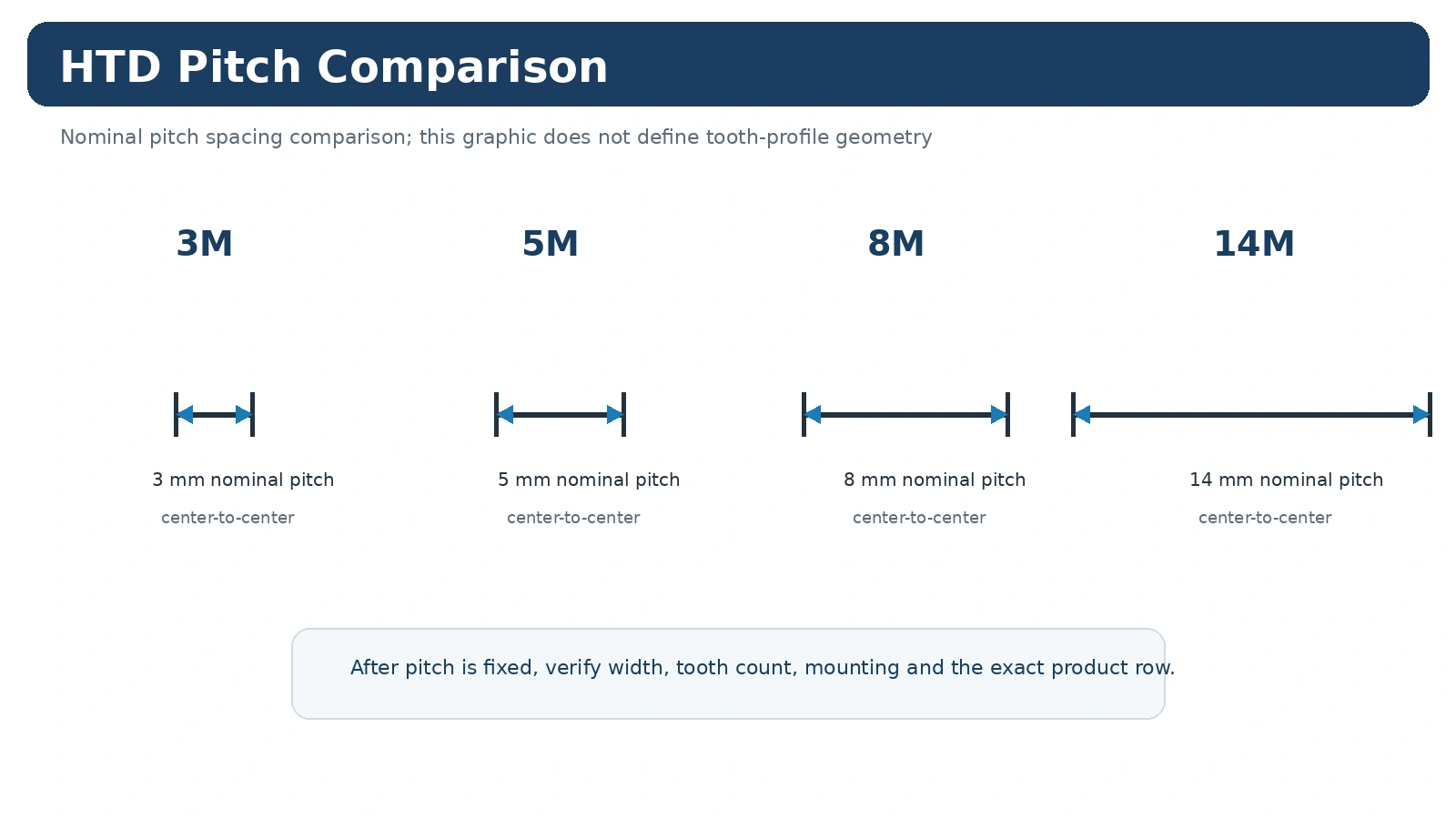
The pulley and belt must use the same HTD pitch family and compatible working width.
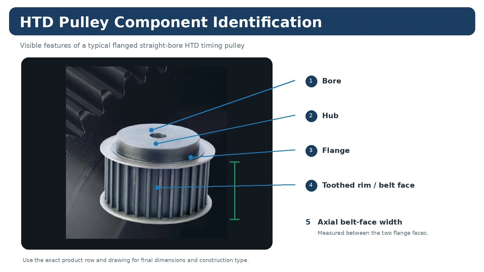
Hub projection, flange position and shaft location must keep the belt in the intended plane.
Contamination, temperature and cleaning conditions influence material and maintenance decisions.
Allow enough access for installation, tension review, inspection and future replacement.
Use Application Context to Improve the Enquiry, Not to Guess the Product
An industry label such as “packaging” or “automation” is not enough to select a pulley. Two machines in the same industry can have very different ratios, center distances, duty cycles and shaft constraints. The application page helps identify the questions to ask; the final selection still returns to the correct product family and its table.
When a machine has recurring failures, include the history in the RFQ. Repeated edge wear, belt replacement frequency, contamination, reversal and recent bearing or shaft work can all change the investigation path. This is more useful than requesting a stronger pulley without describing the failure mode.