Replacement Timing Pulley Checklist for Maintenance Teams should be approached as a drive-system decision. The useful starting point is the mating belt and machine interface, followed by tooth count, working width, shaft mounting and duty conditions. This guide explains the checks that help an engineer or buyer turn replacement timing pulley checklist into an RFQ that can be verified against a catalogue row or drawing.
Identify the Drive Before Comparing Dimensions
For replacement timing pulley checklist, identify the complete belt marking before comparing pulley diameters. HTD is a curvilinear synchronous system and the nominal pitch must stay associated with its profile family. Record the driver and driven tooth counts when an existing ratio must be preserved. For a new drive, document the target speed ratio, driver speed and expected load before choosing tooth counts. This prevents a component-level decision from overriding the machine requirement.
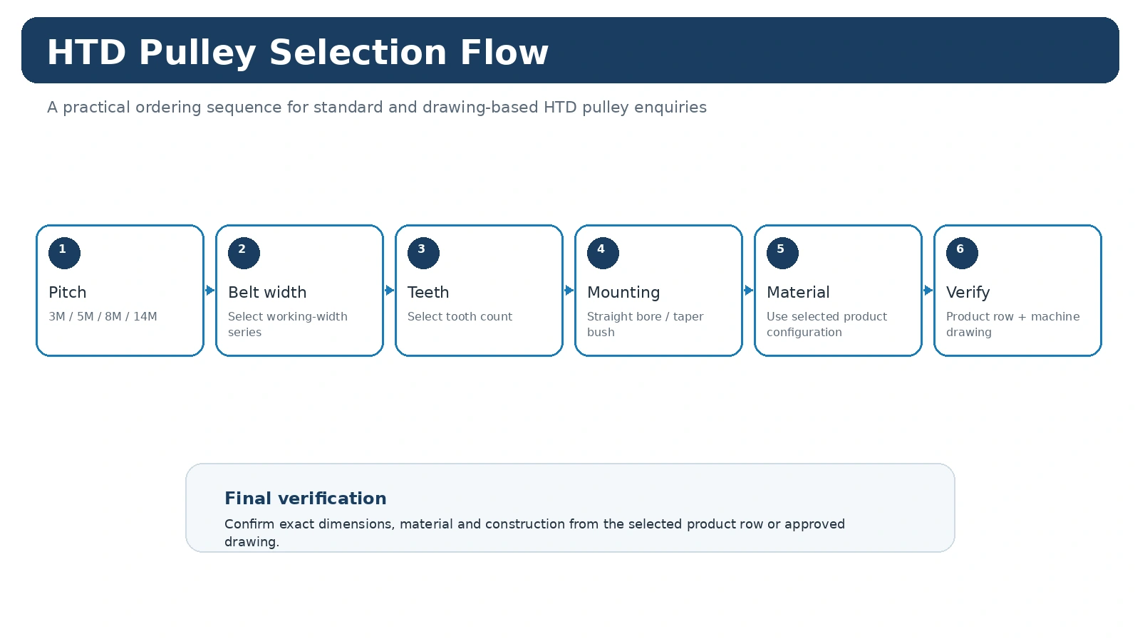
For a replacement project, compare the measured value with the installed belt and machine arrangement before deciding that a catalogue row is equivalent. For a new project, document the design basis so later maintenance teams can understand why the pitch, tooth count and mounting style were selected.
Dimensions That Control the Installation
A pulley can match pitch and tooth count yet still fail to fit the machine because the bore, hub, flange or axial position differs. Measure the shaft interface, belt-face width, hub projection on both sides and the belt line relative to a stable machine datum. Where a taper bush is used, record both the pulley series and bush code. Where a finished bore is required, include fit, keyway and any retaining method on the drawing.
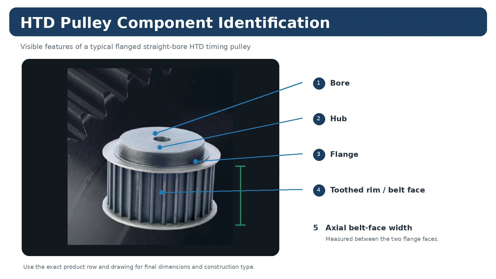
For a replacement project, compare the measured value with the installed belt and machine arrangement before deciding that a catalogue row is equivalent. For a new project, document the design basis so later maintenance teams can understand why the pitch, tooth count and mounting style were selected.
Operating Conditions That Belong in the Selection
The same nominal replacement timing pulley checklist component can see very different service depending on the machine. Starts per hour, reversing, shock loading, continuous operating time, temperature, contamination, cleaning and access for tensioning all influence the drive. A compact automation axis emphasizes repeatable motion and controlled alignment, while a conveyor or process machine may emphasize continuous duty and service access. Supply these conditions instead of asking the pulley to be selected from size alone.
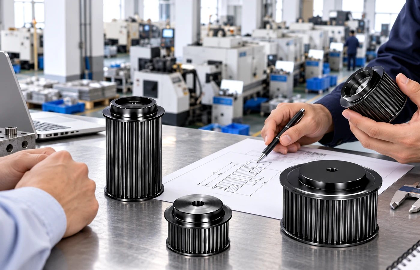
For a replacement project, compare the measured value with the installed belt and machine arrangement before deciding that a catalogue row is equivalent. For a new project, document the design basis so later maintenance teams can understand why the pitch, tooth count and mounting style were selected.
Inspection Points Before Installation
Inspection should focus on dimensions that affect the drive: the shaft interface, axial location, tooth condition, face width and any drawing-controlled runout or datum relationship. A generic quality statement does not define acceptance. If a dimensional report, material document or order-specific record is required, identify it before production. During maintenance, watch for flange damage, edge wear, debris and signs that the pulley has moved on the shaft.

For a replacement project, compare the measured value with the installed belt and machine arrangement before deciding that a catalogue row is equivalent. For a new project, document the design basis so later maintenance teams can understand why the pitch, tooth count and mounting style were selected.
Open Questions to Close Before Ordering
What exact HTD profile and width is installed or specified?
What ratio or existing tooth count must be preserved?
What bore, fit, keyway or taper-bush arrangement is required?
How much hub projection and flange clearance is available?
What are the speed, load, starts, reversing and operating hours?
Which drawing, material or inspection records must accompany supply?
What to Send With the RFQ
Send profile, tooth count, belt width, shaft interface, hub/flange details, quantity, destination and a drawing or replacement measurement sketch. Add speed, ratio, load, center distance and environment for a new drive. Review the HTD product families, use the selection guide, or compare the relevant application notes.
Capture Replacement Data Before Disassembly
The best time to collect information is before the old drive is dismantled. Photograph the belt path, hub orientation, shaft end and guard clearance; then record the belt marking and pulley geometry.
Keep measured values, catalogue references and project requirements clearly separated. If a required point is not stated in the relevant catalogue table or approved drawing, include it as an RFQ question or drawing requirement instead of filling the gap with a plausible but unverified value.
Keep “Measured” and “Catalogue” Values Separate
Field dimensions are useful, but label them as measurements until a catalogue row or drawing confirms what each value represents. This avoids silently converting an outside diameter into a pitch-diameter reference.
The purchasing record should keep a clear link between the machine requirement and the selected pulley. That means the complete belt or profile identity, tooth count, working width and shaft-interface information remain together with the product code. Any special material, finish, controlled tolerance, marking or report requirement should be stated separately so it cannot be mistaken for a universal feature of the whole family.
Procurement and Documentation
Once the selection is clear, keep the accepted product identity, quantity, destination and drawing revision on the same purchase line. Standard catalogue parts are normally planned around production-quantity minimums, while larger or higher-value items can be reviewed against the practical order value. Qualified new-client samples of 1–5 pieces may be reviewed at sample pricing when the configuration and manufacturing route are suitable.
Mixed-model orders can be consolidated toward a practical order value of about USD 1,500. Special materials and special processes follow the minimum quantity required by that process. Very small one- or two-piece requests are handled only as qualified engineering validation or paid-sample cases rather than retail replacement orders.
Lead time is confirmed after the technical definition is clear. Standard parts are typically planned at 10–25 business days, custom components at 20–45 business days, and project-based assemblies or related equipment at 45–120 business days where applicable. EXW, FOB, CIF and DAP are commonly supported; FCA, CFR, CPT, CIP and DDP can be discussed for suitable shipments. Treat these as planning ranges, not a shipment promise before order review.
A Practical Decision Sequence
Start with identity, geometry, belt line, shaft interface and machine context. Keep the machine requirement separate from the catalogue choice: first identify what the drive must preserve, then compare only the rows or drawings that match that identity. This keeps a familiar-looking pulley from being accepted before its functional interfaces have been checked.
For an existing machine, preserve the original relationship before making changes. For a new design, record the target ratio, operating context and installation envelope so the replacement release can be reviewed later without relying on memory or a photograph alone.
Build a Measurement Record
The most useful measurement set contains belt marking, tooth count, face width, bore/bush, hub projection, photos and quantity. Mark which values were measured on the machine and which values came from a catalogue or released drawing. When a feature is inaccessible, photograph its relationship to a stable datum and identify it as confirmation-required rather than filling the gap with an assumed value.
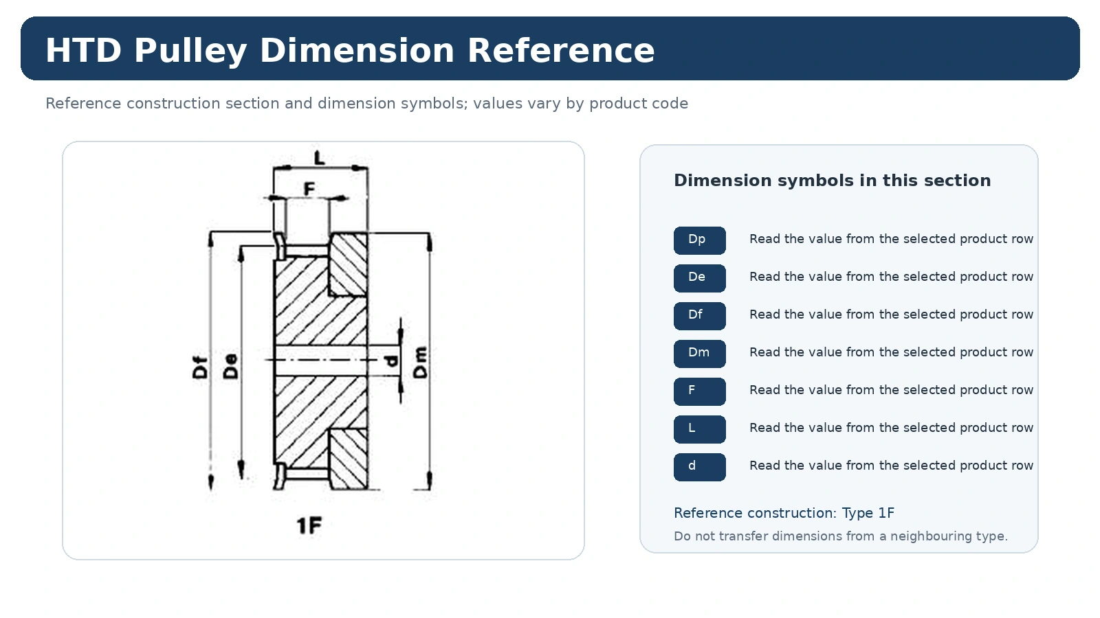
Dimension drawings should be viewed at full readable width. Never scale a screenshot and then treat the scaled dimension as a measurement; use the printed value and the correct construction type.
One Failure Mode Worth Avoiding
A common error is approving a visually similar pulley before checking the installation datums. That can produce a part that appears close in the catalogue yet changes ratio, belt line, mounting or service access. Resolve the conflicting feature before requesting price so the quotation refers to one mechanically coherent configuration.
If two candidate configurations remain possible, send both the machine measurements and photographs and the preferred option. The quotation can then identify which interface still needs confirmation instead of silently converting uncertainty into a specification.
Turn the Technical Choice Into a Quote-Ready Line Item
State the HTD/profile family and complete belt information.
Provide the tooth count, working width and relevant dimension or drawing references.
Define the bore or bush, shaft data, hub projection and belt-line position where applicable.
Add quantity, destination, required documents and the drawing revision used for the request.
When one item above is genuinely unknown, label it for confirmation. A precise open question is more useful than a plausible value that was never measured.
Questions Buyers Commonly Ask
What should be confirmed first?
Confirm identity, geometry, belt line, shaft interface and machine context. That prevents later dimensions from being compared across the wrong product family or installation route.
What information is most useful for a replacement?
Send belt marking, tooth count, face width, bore/bush, hub projection, photos and quantity, plus clear photographs before the old pulley is removed. The photographs preserve axial orientation and neighboring clearances that a loose part cannot show.
When should a drawing be used?
Use a controlled drawing whenever the catalogue row does not completely define the shaft interface, hub/flange arrangement, finish, tolerance or inspection requirement that matters to the machine.
Diagnose the System Before Replacing the Pulley
Tracking, edge wear, noise or repeated belt damage can have more than one cause. Before ordering a new pulley, inspect alignment, shaft and bearing condition, mounting security, belt condition, contamination and the position of the belt relative to the flanges. A visible symptom at the pulley is not by itself proof that the pulley geometry is the root cause.
For replacement work, document the installed condition first. Photograph both pulley faces and the belt path, record the belt marking and tooth count, and note whether the symptom appears under load, on reversal or after warm-up. Those observations make it easier to separate an installation problem from a worn or incorrect component.
Turn the Finding Into a Controlled Repair
If a pulley is replaced, keep the accepted model or drawing revision with the maintenance record. Record any shaft or hub machining performed during the repair so the next replacement does not assume the original catalogue interface still exists. If runout or a dimensional characteristic is functionally critical, define the measurement reference and acceptance value on the repair drawing or purchase requirement.
After installation, verify belt line and the drive condition before the machine returns to normal service. The goal is not simply to fit a new component; it is to restore a traceable and serviceable drive configuration.
Build the Replacement Record Before the Machine Is Taken Apart
The maintenance team should capture the installed relationship before the pulley is removed. Photograph both faces and the belt path, record the belt marking, count the teeth, measure the working width and note shaft shoulders, spacers, hub projection and guard clearance. Mark which measurements are direct field readings and which come from a catalogue or drawing.
After disassembly, inspect wear without losing orientation. A polished flange, damaged keyway, fretted bush or uneven tooth surface can reveal why the old part failed, but those findings should not overwrite the identification record. Correct the underlying alignment, shaft or contamination issue separately from selecting the replacement component.
When the new part is ordered, keep the final product code and drawing revision with the maintenance file. That makes the next replacement a controlled comparison instead of a fresh reverse-engineering exercise.
Do a Side-by-Side Acceptance Check Before the Old Part Is Discarded
Where practical, keep the old pulley until the replacement has been compared against it and against the machine record. Check tooth family, count, working face, bore or bush, hub projection and flange orientation side by side. Use the catalogue drawing to decide which dimensions are nominal references and which measurements should be taken directly from the installed machine.
Do not let visible wear become the template for the new component. A widened keyway, polished flange or damaged bore should be recorded as a condition finding. The replacement should follow the correct catalogue row or released drawing, while the maintenance action separately addresses the reason the old part became damaged.
Capture the Installed Relationship Before You Order the Spare
A successful replacement preserves more than the outside diameter. Before removal, document the belt marking, tooth count, working width, shaft interface, hub projection, flange arrangement and the pulley position relative to guards and adjacent components. These details turn an old part into a controlled replacement record rather than a loose sample.
The removed component may be worn, modified or previously remachined, so do not treat every measured dimension as nominal. Compare measurements with the selected catalogue row and use the machine-side geometry to identify which features must remain unchanged. If the original product code is unreadable, photographs from both sides are especially useful.
Belt marking, pitch family, tooth count and width.
Bore or bush, shaft diameter, keyway and retaining features.
Hub projection, flange diameter, total width and belt-line position.
Wear pattern, looseness, tracking marks and the reason the part is being replaced.
Keep the accepted replacement code or drawing with the machine record after installation. Future maintenance becomes much easier when the selected part and the measurements that justified it are stored together.