HTD-Steuerriemenscheiben für Werkzeugmaschinen Die Auswahl sollte anhand der Maschinenbelastung und des Riemensystems erfolgen, nicht allein anhand des Durchmessers. Bei Hilfsachsen, Spindelantrieben und Präzisionsmaschinenbewegungen hängen die Genauigkeit und Wartungsfreundlichkeit der Zahnriemenscheiben von der kompletten Anordnung aus Welle, Riemen, Lager und Spannvorrichtung ab.
Maschinenkontext und Arbeitszyklus
Erfassen Sie Antriebsgeschwindigkeit, Abtriebsgeschwindigkeit bzw. Übersetzungsverhältnis, erwartetes Drehmoment bzw. Leistung, Starts pro Stunde, Rückwärtslauf, Achsabstand und Betriebsstunden. Dokumentieren Sie außerdem Verschmutzungsgrad, Temperatur, Reinigungsintervalle bzw. Staubbelastung sowie die Zugänglichkeit für Wartungsarbeiten. Anhand dieser Daten ist zu entscheiden, ob für das Projekt eine Standard-Riemenscheibe aus dem Katalog verwendet oder eine zeichnungsgesteuerte Schnittstelle eingesetzt werden sollte.
Auswahlvariablen
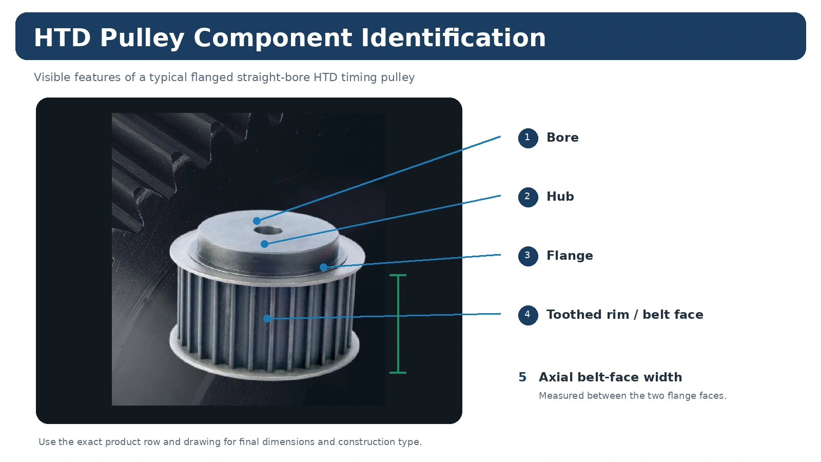
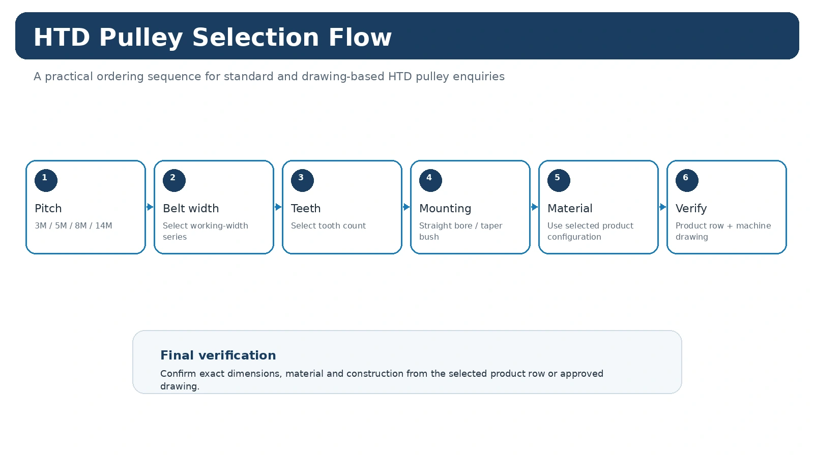
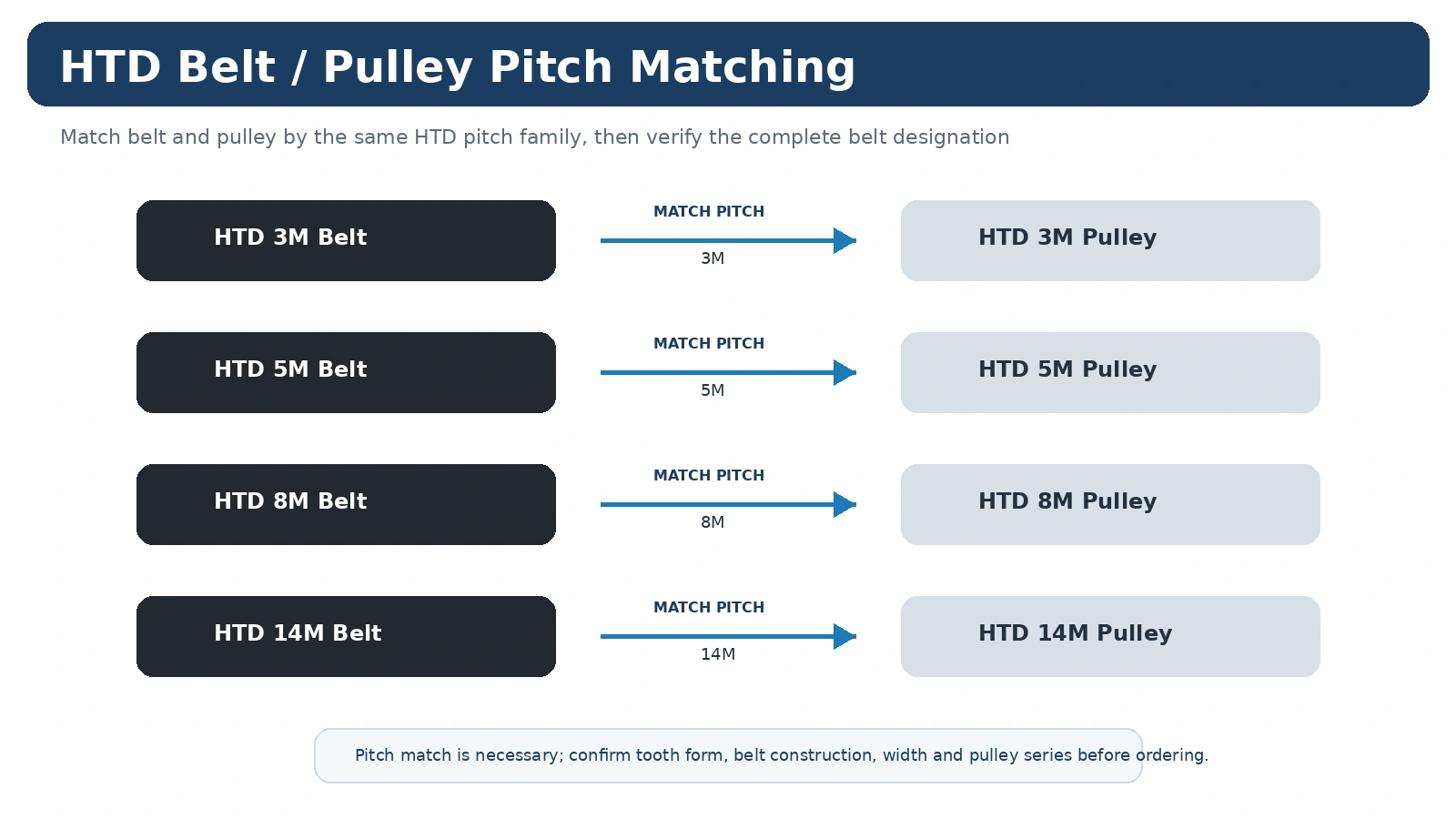
Bestätigen Sie zunächst die genaue HTD-Riemenfamilie. Wählen Sie anschließend die Zähnezahl, die Arbeitsbreite und die Wellenbefestigung. 3M und 5M eignen sich für kompakte Antriebe; 8M und 14M decken größere industrielle Anlagen ab. Die endgültige Wahl hängt jedoch von der Antriebsberechnung und den Riemendaten ab. Nabenüberstand und Flanschanordnung müssen zu den Abmessungen der Maschine passen.
Integrations- und Sicherheitsprüfungen
Richten Sie die Riemenscheiben und Wellen aus, halten Sie Schutzvorrichtungen und angrenzende Bauteile vom Riemenlauf fern und verwenden Sie die Vorgaben des Riemenherstellers oder der Maschinenkonstruktion zur Riemenspannung. Überprüfen Sie nach der Inbetriebnahme den Kantenlauf und den Riemenscheibenhalt. Wenn der Antrieb eine sicherheitskritische Funktion erfüllt, wenden Sie die Risikobewertungs- und Validierungsanforderungen des Maschinenbauers an und verlassen Sie sich nicht auf ein allgemeines Bauteildatenblatt.
RFQ-Vorbereitung
Senden Sie die Riemenkennzeichnung, das gewünschte Übersetzungsverhältnis bzw. die Zähnezahl der Riemenscheibe, die Riemenbreite, die Wellenschnittstelle, den Achsabstand, die Angaben zum Betriebspunkt, die Menge sowie eine Zeichnung oder Maschinenskizze. HTD-Riemenscheibenfamilien, verwenden Sie die Auswahlhilfeoder Rezension Inspektionsplanung vor der Bestellung.
Die jeweilige Werkzeugmaschinenachse definieren
Die Einsatzmöglichkeiten von Werkzeugmaschinen reichen von Hilfsantrieben bis hin zu Positioniermechanismen. Daher ist der sinnvolle Ausgangspunkt die eigentliche Achse: Riemenfamilie, Drehzahlverhältnis, Wellenanordnung, Belastung und verfügbarer Bauraum.
Bei Ersatzteilen sind die Maße beider Seiten und die Riemenlinie beizubehalten. Wenn Rundlauf, Passung oder Prüfung kontrolliert werden müssen, sind die Bezugspunkte und Abnahmekriterien in der Auftragszeichnung anzugeben, anstatt sich auf eine allgemeine „Präzisionsangabe“ zu verlassen.
Übersetzung der Maschinenbelastung in eine Riemenscheiben-Anfrage
Bei Hilfsachsen, Werkzeughandhabungsmechanismen und gesteuerten Maschinenbewegungen sollte die Riemenscheibe als Teil des Synchronantriebs und nicht als isoliertes Rad ausgewählt werden. Erfassen Sie die Drehrichtungsumkehr, die Späne-/Kühlmittelbelastung, den Schutzabstand und den Zustand der Wellenlagerung. Geben Sie bei einem neuen Antrieb zusätzlich die Antriebsdrehzahl, die erforderliche Abtriebsdrehzahl bzw. das Übersetzungsverhältnis, das Drehmoment bzw. die Leistung, den Achsabstand und die Betriebsstunden an. Diese Angaben definieren den Einsatzbereich der Riemenfamilie und der Zähnezahl; sie ersetzen nicht die Kataloggeometrie.
Für Austauscharbeiten fotografieren Sie vor der Demontage den installierten Riemenverlauf und beide Seiten der Riemenscheibe. Die Riemenmarkierung, die Lauffläche, die Zähnezahl, die Wellenschnittstelle und der Nabenüberstand sind in der Regel aussagekräftiger als der Außendurchmesser allein.
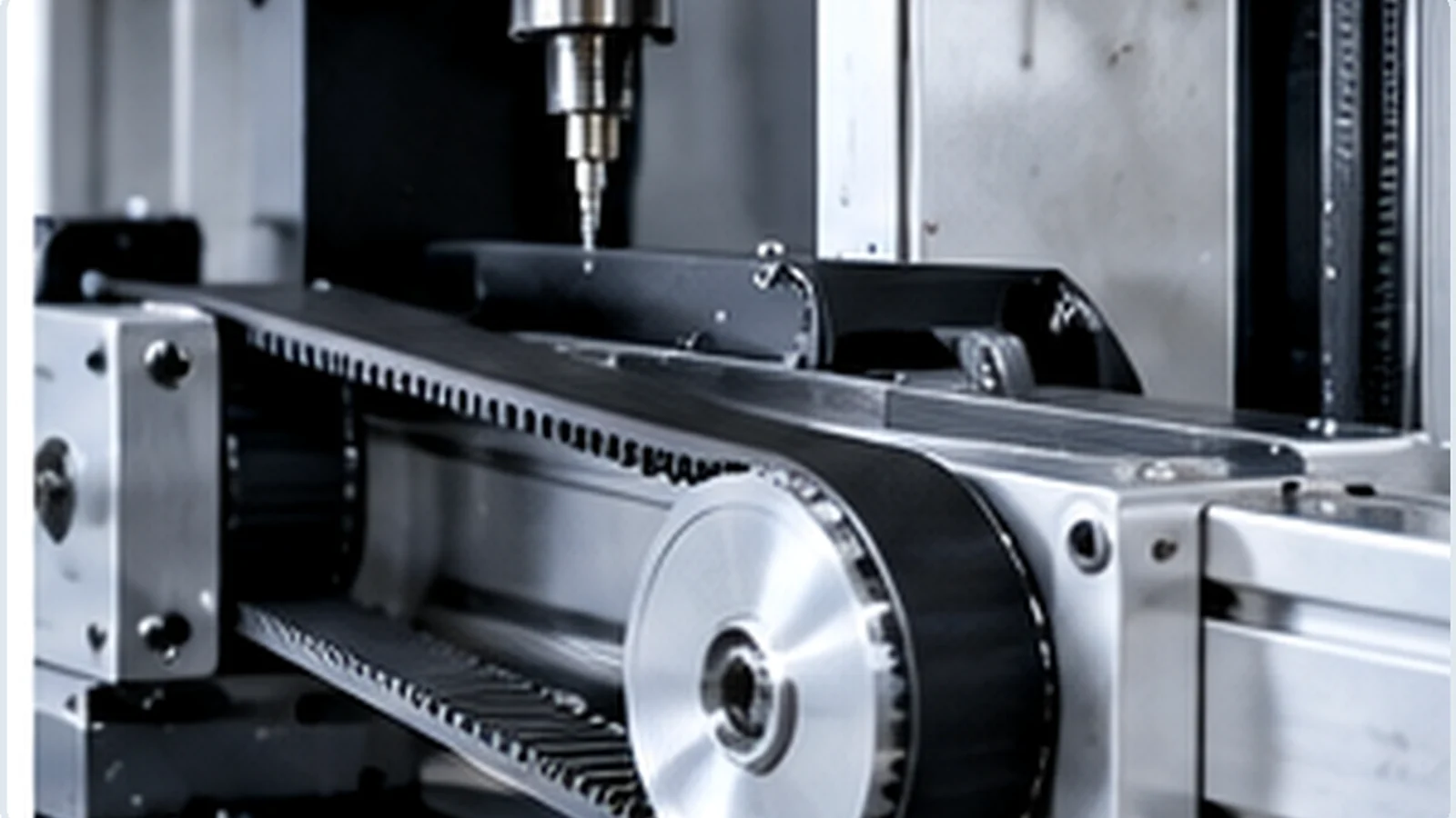
Integrationsprüfungen vor der Veröffentlichung
Prüfen Sie, ob die gewählte Riemenscheibe den Riemen in der vorhandenen Maschinenebene hält und genügend Freiraum für Schutzvorrichtungen, Lager und angrenzende Bauteile lässt. Überprüfen Sie, wie das Bauteil montiert und demontiert werden kann; eine ansonsten korrekte Nabe kann unpraktisch sein, wenn sie den Wartungszugang behindert.
Wenn die Anwendung wiederholt Probleme mit dem Laufverhalten, dem Kantenverschleiß oder der Spannung aufweist, sollten diese Symptome dokumentiert werden, bevor die Riemenscheibengeometrie geändert wird. Ausrichtung, Lagerlagerung, Wellenzustand und Montage können Symptome hervorrufen, die nicht automatisch der Riemenscheibe zugeschrieben werden sollten.
Was Sie der Anfrage beifügen sollten
Geben Sie die vollständige HTD- oder Riemenbezeichnung, Zähnezahl, Arbeitsbreite, Bohrungs- oder Kegelbuchseninformationen, Menge und Bestimmungsort an. Fügen Sie bei einer Neumaschine die wichtigsten Betriebsdaten hinzu; bei einem Ersatzteil Fotos und die Abmessungen des alten Teils. Tragen Sie alle speziellen Material-, Oberflächen-, Toleranz- oder Prüfanforderungen in die Zeichnung ein, damit diese mit der ausgewählten Produktfamilie abgeglichen werden können.
Wichtige Wartungsinformationen für HTD-Steuerriemenscheiben für Werkzeugmaschinen
Nach der Inbetriebnahme des Antriebs sind die Bezeichnung des installierten Riemens, die Riemenscheibenserie, die Zähnezahl und die Montagedetails in der Maschinendokumentation zu dokumentieren. Jegliche Zeichnungsrevisionen, die für eine kundenspezifische Nabe oder Bohrung verwendet wurden, sind zu vermerken. Sollte ein späterer Wartungsvorgang die Welle, die Buchse oder die Riemenfamilie ändern, ist der Datensatz zu aktualisieren, anstatt sich auf die alte Kaufhistorie zu verlassen.
Diese kleine Aufzeichnung macht die Fehlersuche bei zukünftigen Reparaturen zuverlässiger, da die Wartung zwischen normalem Verschleiß und einer Konfigurationsänderung, die bei einer früheren Reparatur aufgetreten ist, unterscheiden kann.
Bedienungsfragen zum Werkzeugmaschinenantrieb
Vor der Auswahl einer Riemenscheibenfamilie müssen Motor-/Spindel- bzw. Achsendrehzahlen, Drehrichtungsumkehrungen, Achsabstand, Gehäusefreiheit, Wellenlagerung und erforderliche Prüfgrenzen dokumentiert werden. Diese Angaben definieren die Anforderungen an den Synchronantrieb. Mithilfe der Produkttabelle lassen sich dann Zähnezahlen, Breitenreihen und Montagegeometrien vergleichen, anstatt die Kapazität allein anhand der Anwendungsbezeichnung zu bestimmen.
Das praktische Ziel ist eine wiederholbare Hilfsbewegung und kontrollierte Wellenverbindungen. Überprüfen Sie den gesamten Antrieb nach jeder geplanten Änderung, da Rundlauf, Wellenpassung und Nabensteifigkeit den Maschinen- oder Zeichnungsspezifikationen und nicht einem allgemeinen Richtwert entsprechen sollten. Falls für eine bestehende Maschine keine Zeichnung vorliegt, bewahren Sie die Riemenmarkierungen und Fotos vor dem Ausbau zusammen mit den Messdaten auf, damit der Ersatz mit der tatsächlichen Installation verglichen werden kann.
Installations- und Wartungskontext
Prüfen Sie den Riemenverlauf von der Antriebs- zur Abtriebsscheibe, vergewissern Sie sich, dass die Wellen richtig gelagert und ausgerichtet sind, und stellen Sie sicher, dass Schutzvorrichtungen, angrenzende Bauteile und Wartungswerkzeuge ausreichend Freiraum haben. Eine maßlich passende Riemenscheibe kann dennoch ungeeignet sein, wenn eine längere Nabe, eine andere Buchse oder eine andere Flanschanordnung den Riemen aus seiner ursprünglichen Ebene verschiebt.
Prüfen Sie bei der Wartung den Zustand von Zähnen und Flansch sowie den Riemenverschleiß. Ungewöhnlicher Kantenverschleiß, Staubablagerungen oder wiederholte Spurkorrekturen können auf ein Ausrichtungs-, Abstütz- oder Verschmutzungsproblem hinweisen, das vor dem Einbau des neuen Bauteils behoben werden sollte.

RFQ-Daten für den Werkzeugmaschinenantrieb
Bitte senden Sie die HTD-/Profilfamilie, die Zähnezahl, die Riemenbreite, die Wellen- oder Buchseninformationen, die Menge und den Bestimmungsort. Bei einem neuen Antrieb geben Sie bitte zusätzlich die Drehzahlkennlinie, den Achsabstand und die Betriebsbedingungen an. Bei Austauscharbeiten fügen Sie bitte aussagekräftige Fotos und die Maße bei, die die Riemenlaufbahn und die Nabenposition bestimmen. Tragen Sie alle speziellen Anforderungen an Material, Oberflächenbehandlung, Kennzeichnung, Prüfung oder Dokumentation vor der Produktionsfreigabe in die Angebotsanfrage oder die Zeichnung ein.