HTD 14M-115 Conische bus distributiepoelie
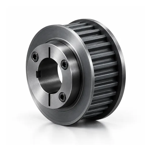
14M HTD distributiepoelie uit de 14M-115 serie met conische bus. Selecteer het aantal tanden en de bijbehorende buscode in de catalogus.
Overzicht van de configuratie van de HTD 14M-115 conische distributiepoelie
14M-115 HTD distributiepoelie Dit is een serie synchrone poelies met een steek van 14 mm en een nominale riemvlakreferentie van 115 in het catalogusnaamgevingssysteem. Op deze pagina wordt de serie behandeld als een configureerbaar industrieel component in plaats van een vast artikelnummer. Het aantal tanden beïnvloedt de poeliediameter en kan ook de naaf, flens, materiaal of montagegegevens beïnvloeden. Daarom moet de bestelling gekoppeld worden aan een specifieke catalogusregel of een goedgekeurde tekening.
Begin bij de aanschaf met de volledige riemaanduiding en controleer of de bijbehorende riem hetzelfde HTD 14M-profiel heeft. De steek alleen is geen betrouwbare uitwisselregel voor elke riemfamilie met een gebogen profiel. Selecteer na bevestiging van het profiel het aantal tanden en de werkbreedte, en controleer vervolgens de asinterface, de naafuitsteeksel, de flensconfiguratie en het beschikbare materiaal. Deze volgorde vermindert de veelvoorkomende fout bij vervanging, waarbij alleen de buitendiameter wordt vergeleken en het tandsysteem of de montagegeometrie over het hoofd wordt gezien.
De getoonde conische busbevestiging voor deze serie is bedoeld voor positieve synchrone krachtoverbrenging. Typische aanvragen komen van grotere industriële aandrijvingen, textiel-/papiermachines en zware synchrone transmissies. De daadwerkelijke geschiktheid hangt af van de snelheid, de overgedragen belasting, de hartafstand, de riemconstructie, de uitlijning, de omgeving en de asondersteuning. Deze gegevens moeten worden opgegeven voor een nieuwe aandrijving of wanneer een bestaande machine terugkerende problemen met riemgeleiding of slijtage vertoont.
14M-115 Constructie en schachtinterface
14M-115 Dit product behoort tot de 14M HTD-familie en deze pagina behandelt de montage met conische bus. De catalogustabel op deze pagina omvat 28 tot en met 192 tanden. Constructiecodes die in de tabel zichtbaar zijn, zijn onder andere 18F, 19F, 19 en 20. Gebruik de exacte productcode met het aantal tanden, omdat de naaf/flens-configuratie binnen één breedteserie kan variëren.
De breedtecode 115 Deze catalogusfamilie wordt hiermee geïdentificeerd; het is geen vervanging voor het controleren van de markering op de bijbehorende riem en de maattekening. Bij vervangingswerkzaamheden dient u de geïnstalleerde riemlijn te behouden en de geometrie aan de aszijde op te meten voordat u besluit of een rij met de juiste tanden een geschikte mechanische vervanging is.
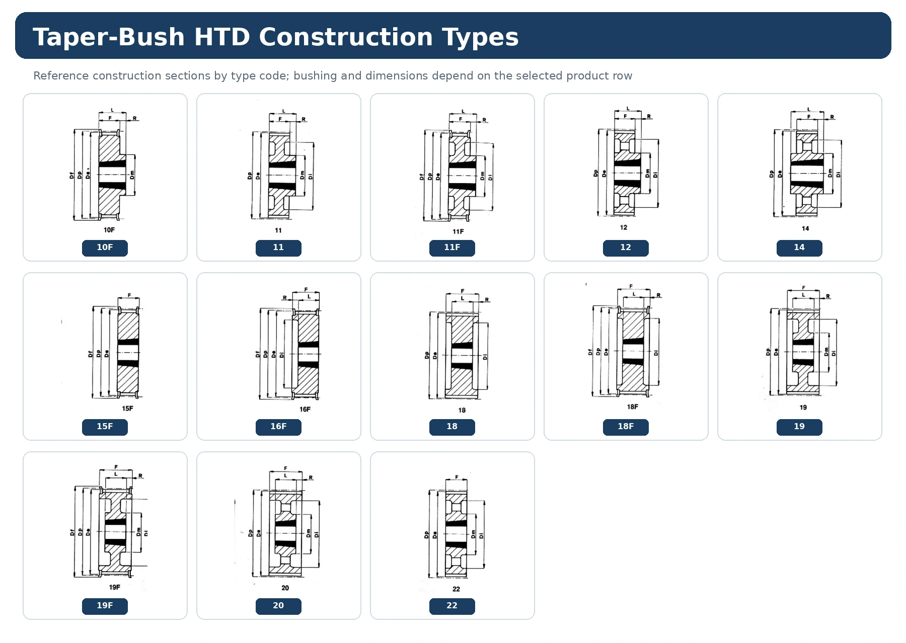
Lees de 14M-115 dimensieweergave vóór de tabel.
De maataanduiding laat zien hoe symbolen zoals Dp, De, Df, Dm, Di, F, L en boringgerelateerde velden zich verhouden tot de constructietekening. Gebruik de tekening en dezelfde productregel samen; neem geen maataanduiding over van een ander constructietype, alleen omdat de steek en het aantal tanden overeenkomen.
Voor 14M-115 dient u de waarden die de installatie bepalen – werkvlak, naafuitsteeksel, flensomhulsel en asverbinding – vast te leggen ten opzichte van een stabiel machinereferentiepunt. Indien een afgewerkte boring, spiebaan of tolerantie niet is gedefinieerd in de catalogusregel, voeg deze dan toe aan de offerteaanvraag of gecontroleerde tekening in plaats van een universele waarde aan te nemen.
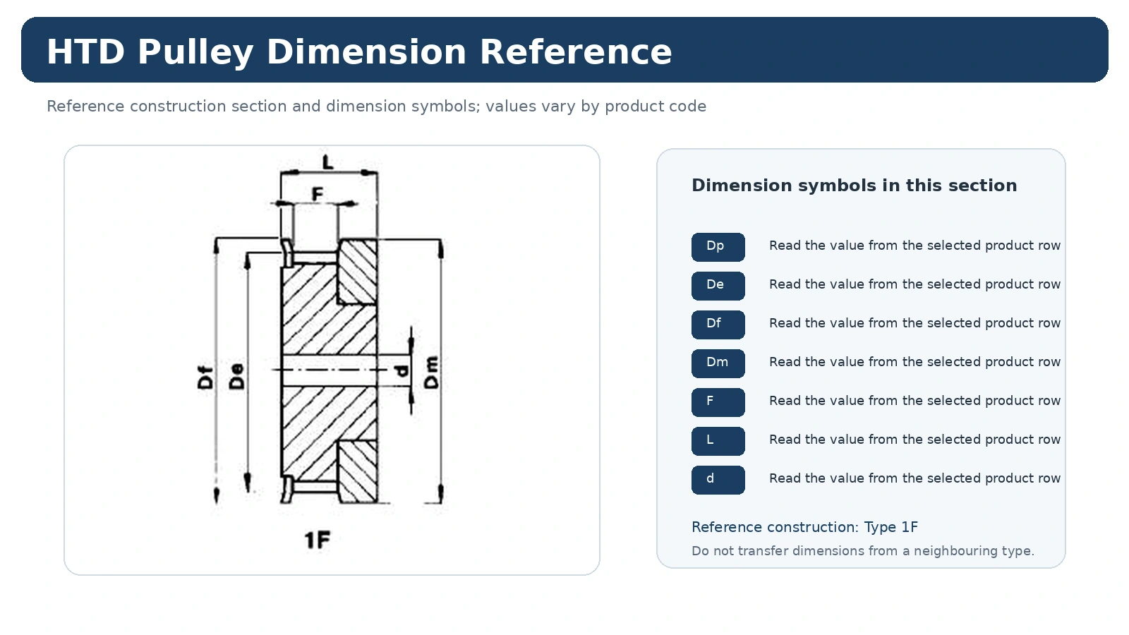
Bush-selectie: Deze tabel 14M-115 bevat busreferenties zoals 2517, 3020, 3030, 3535 en 4040. De busreferentie verschilt per productregel; controleer het exacte aantal tanden en de asdiameter in plaats van aan te nemen dat één bus de hele serie dekt.
14M-115 Technische specificatietabel
De volgende waarden zijn overgenomen uit de catalogus van de geselecteerde distributiepoelie voor deze serie. Gebruik de code en het aantal tanden samen bij het aanvragen van een offerte. De afmetingen zijn cataloguswaarden; de uiteindelijke passing van de as, de spiebaan, de oppervlakteafwerking en de inspectie-eisen moeten worden vermeld in de offerteaanvraag of op de tekening.
| Code | Type | Tanden | Struik | Maximale boring | Dp | De | Df | Dm | Di | F | L | R | Flens | Ongeveer kg |
|---|---|---|---|---|---|---|---|---|---|---|---|---|---|---|
| TL 28-14M-115 | 18F | 28 | 2517 | 60 | 124,78 | 122,12 | 127 | – | 98 | 133 | 45 | 44 | 400 | 3,80 |
| TL 30-14M-115 | 18F | 30 | 2517 | 60 | 133,69 | 130,99 | 138 | – | 100 | 133 | 45 | 44 | 401 | 5,00 |
| TL 32-14M-115 | 18F | 32 | 2517 | 60 | 142,60 | 139,88 | 154 | – | 108 | 133 | 45 | 44 | 403 | 6,80 |
| TL 34-14M-115 | 18F | 34 | 2517 | 60 | 151,52 | 148,79 | 160 | – | 110 | 133 | 45 | 44 | 404 | 6,90 |
| TL 36-14M-115 | 18F | 36 | 3020 | 75 | 160,43 | 157,68 | 168 | – | 125 | 133 | 51 | 41 | 405 | 7,00 |
| TL 38-14M-115 | 18F | 38 | 3020 | 75 | 169,34 | 166,60 | 183 | – | 130 | 133 | 51 | 41 | 406 | 8,50 |
| TL 40-14M-115 | 18F | 40 | 3020 | 75 | 178,25 | 175,49 | 188 | – | 138 | 133 | 51 | 41 | 407 | 9,10 |
| TL 44-14M-115 | 18F | 44 | 3030 | 75 | 196,08 | 193,28 | 211 | – | 155 | 133 | 76 | 28,5 | 411 | – |
| TL 56-14M-115 | 18F | 56 | 3535 | 90 | 249,55 | 246,76 | 256 | – | 210 | 133 | 89 | 22 | 416 | – |
| TL 64-14M-115 | 19F | 64 | 3535 | 90 | 285,21 | 282,41 | 296 | 190 | 240 | 133 | 89 | 22 | 418 | – |
| TL 72-14M-115 | 19 | 72 | 3535 | 90 | 320,86 | 318,06 | – | 190 | 280 | 133 | 89 | 22 | – | – |
| TL 80-14M-115 | 20 | 80 | 3535 | 90 | 356,51 | 353,71 | – | 190 | 315 | 133 | 89 | 22 | – | 32,00 |
| TL 90-14M-115 | 20 | 90 | 3535 | 90 | 401,07 | 398,28 | – | 190 | 360 | 133 | 89 | 22 | – | 37,00 |
| TL 112-14M-115 | 20 | 112 | 3535 | 90 | 499,11 | 496,32 | – | 190 | 457 | 133 | 89 | 22 | – | 45,00 |
| TL 114-14M-115 | 20 | 144 | 4040 | 100 | 641,71 | 638,92 | – | 230 | 600 | 133 | 102 | 15,5 | – | – |
| TL 168-14M-115 | 20 | 168 | 4040 | 100 | 748,66 | 745,87 | – | 230 | 706 | 133 | 102 | 15,5 | – | – |
| TL 192-14M-115 | 20 | 192 | 4040 | 100 | 855,62 | 852,82 | – | 230 | 813 | 133 | 102 | 15,5 | – | 95,00 |
Waar past de 14M-115-familie in?
De 14M-115 maakt deel uit van de 14M-familie en wordt gebruikt voor grotere HTD-aandrijvingen waarbij de naaf, flens, asinterface, massa en onderhoudstoegankelijkheid steeds belangrijker worden bij de installatieplanning. De geschiktheid voor een toepassing wordt niet alleen bepaald door de steek. Voor een nieuwe aandrijving moeten ook de vereiste snelheidsverhouding, belasting- of koppelbasis, hartafstand, omgeving en bedrijfsomstandigheden worden vastgesteld voordat de poelierij definitief kan worden bepaald.
Bij een vervanging is het het veiligst om uit te gaan van de bestaande riem/profielidentificatie plus het oorspronkelijke aantal tanden. Het wijzigen van het aantal tanden verandert de steekdiameter en de overbrengingsverhouding, terwijl het wijzigen van de montageconstructie de riemlijn kan verplaatsen of de toegankelijkheid voor demontage kan beïnvloeden.
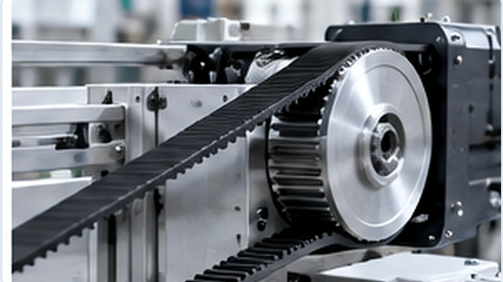
Materiaal- en constructiekeuzes voor 14M-115
Gebruik het materiaal en de constructie zoals weergegeven voor de exacte productcode 14M-115 of de goedgekeurde tekening. Bepaal het materiaal van de poelie niet aan de hand van kleur, oppervlaktekenmerken of een foto. Indien een project een ander materiaal, afwerking, naaf, flens of as-eigenschap vereist, beschouw dit dan als een maatwerkvereiste en beoordeel de invloed hiervan op de afmetingen en inspectie voordat u een offerte uitbrengt.
Binnen het bereik van 28 tot 192 tanden kunnen de constructiecodes variëren. Die variatie is de reden waarom de productcode, het aantal tanden en de constructietekening in het orderrecord bij elkaar moeten blijven.
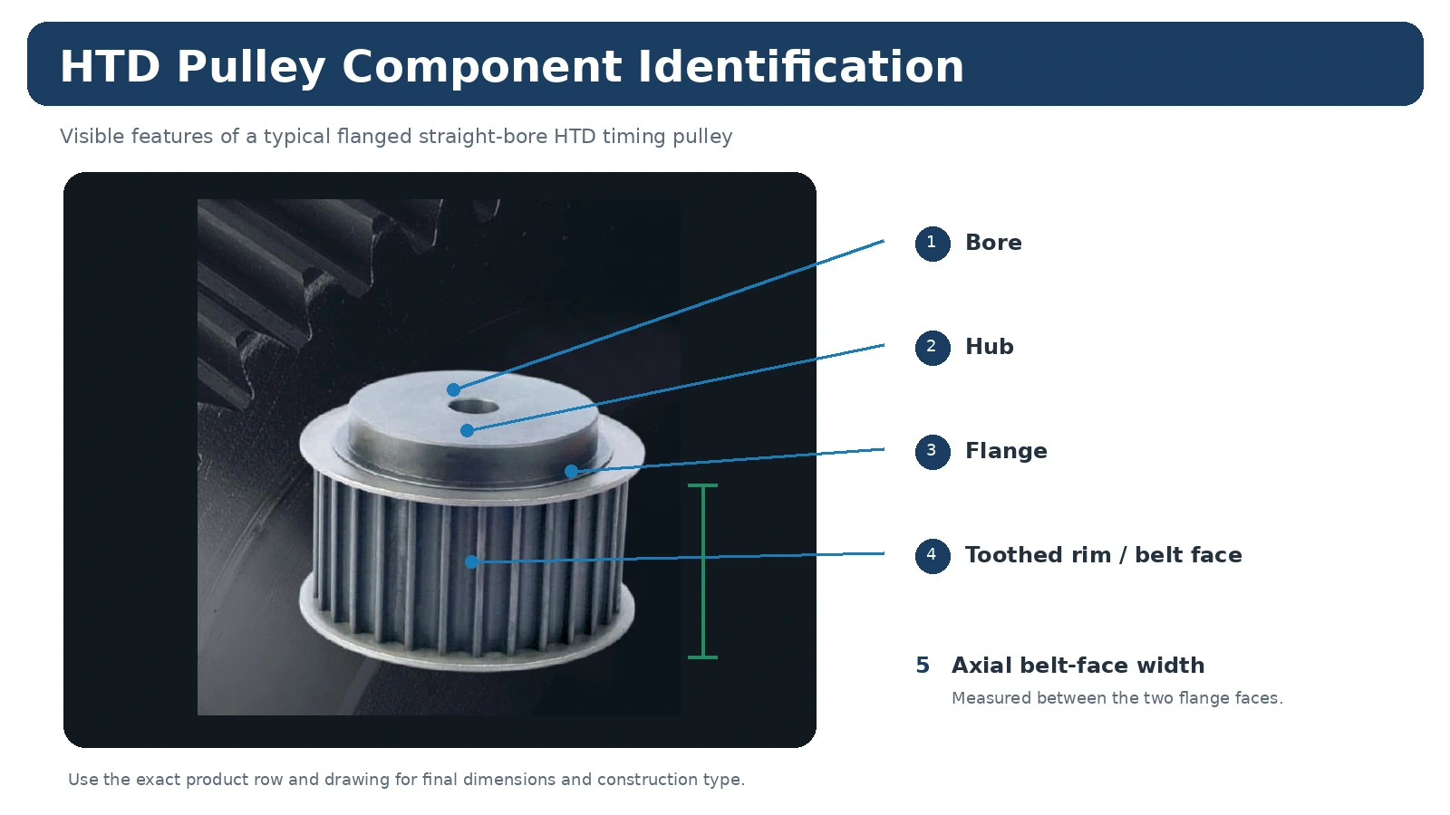
Installatiecontroles voor 14M-115
Vergelijk de nieuwe poelie vóór installatie met de vrijgegeven 14M-115-reeks of -tekening. Controleer de asverbinding, de axiale positie, de staat van de flens en de riemrichting voordat de spanning wordt aangebracht. De riem moet de poelie in kunnen zonder zijdelings te worden gedrukt door een verkeerd uitgelijnde as, een verschoven naaf of een onjuiste afstandhouder.
Controleer na de montage de eigenschappen die van belang zijn voor de daadwerkelijke machine: veilige bevestiging, uitlijning, vrije rotatie, riemgeleiding en eventuele door de tekening bepaalde slingering of axiale positie. Pas geen algemene tolerantie toe wanneer de apparatuur of ordertekening een andere eis stelt.
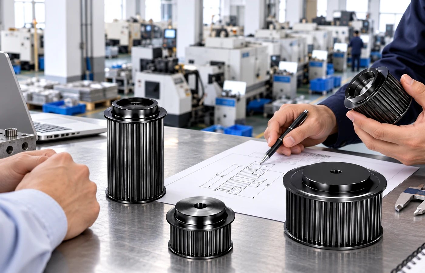
Bestellen, monsters en commerciële planning
De minimumhoeveelheden worden vastgesteld op basis van het producttype, de productieroute en de totale orderwaarde. Standaard catalogusonderdelen vallen doorgaans onder de minimumproductiehoeveelheden.
Nieuwe klanten kunnen 1 tot 5 proefexemplaren aanvragen als de configuratie en het productieproces dit toelaten. Voor de proefexemplaren wordt een aparte offerte opgesteld.
Verschillende katrolmodellen kunnen worden gecombineerd. Een gecombineerde orderwaarde van ongeveer 1.500 USD is het gebruikelijke uitgangspunt voor bestellingen van gemengde modellen.
Een- of tweestuksbestellingen kunnen alleen worden overwogen voor technische validatie of als betaald proefexemplaar, niet als detailbestelling; de prijs per stuk is dienovereenkomstig hoger.
Standaardonderdelen: doorgaans 10-25 werkdagen. Componenten op maat: doorgaans 20-45 werkdagen. Projectgebonden assemblages of bijbehorende apparatuur: 45-120 werkdagen, indien van toepassing. De definitieve levertijd wordt vastgesteld na beoordeling van de tekening, het materiaal en de hoeveelheid.
EXW, FOB, CIF en DAP zijn gangbare leveringsopties. FCA, CFR, CPT, CIP en DDP kunnen worden besproken voor geschikte zendingen en bestemmingen.
Hoe stel je een offerteaanvraag (RFQ) op voor 14M-115?
Stuur de volledige riemmarkering, het vereiste aantal tanden, de riembreedte, de asdiameter en -passing, de montagemethode, de hoeveelheid en de bestemming mee. Voeg een maattekening of duidelijke foto's van de vervangende riem toe als de naafuitsteeksel, flensgeometrie, spiebaan, afwerking of inspectielimieten niet standaard zijn. Als u een verouderde riemschijf vervangt, vermeld dan de afmetingen van de voor-, achter- en zijkant in plaats van alleen de buitendiameter te gebruiken.
Vergelijk voor verwante beslissingen de 14M productfamilie, bekijk de HTD-poelie selectiegids, of zie aanvraagrichtlijnen voor machinespecifieke overwegingen.
14M-115 Veelgestelde vragen
Zijn alle 14M-115 katrollen onderling verwisselbaar?
Nee. De seriecode beperkt de steek- en breedtefamilie, maar het aantal tanden, het constructietype, de boring of bus, de naafafmetingen, de flensconfiguratie en het materiaal kunnen verschillen. Raadpleeg de exacte catalogusregel of tekening.
Kunt u een offerte maken op basis van een bestaande katrol?
Ja, mits de vervangende informatie voldoende is. Stuur de riemmarkering, het aantal tanden, de breedte van het riemvlak, asgegevens en afmetingen van beide zijden. Een tekening heeft de voorkeur bij niet-standaard geometrie.
Kunnen kleine hoeveelheden worden geleverd?
Kleine betaalde proefmonsters kunnen in aanmerking komen voor gekwalificeerde technische validatie. De normale verkooproute loopt via levering aan de industriële productie, in plaats van via de detailhandel (één of twee stuks per keer).
Welke documenten moeten bij de bestelling worden opgevraagd?
De staat vereist dimensionale inspectie, materiaaldocumentatie, markering of orderspecifieke conformiteitsdocumenten in de offertefase, zodat de beschikbaarheid en de omvang van de bestelling vóór de productie kunnen worden bevestigd.