Cara Memilih Takal Pemasaan HTD Taper Bush harus didekati sebagai keputusan sistem pemacu. Titik permulaan yang berguna ialah antara muka tali sawat dan mesin yang sepadan, diikuti dengan kiraan gigi, lebar kerja, pemasangan aci dan keadaan tugas. Panduan ini menerangkan pemeriksaan yang membantu jurutera atau pembeli menukar pemilihan takal pemasaan semak tirus kepada RFQ yang boleh disahkan terhadap baris atau lukisan katalog.
Kenal pasti Pemacu Sebelum Membandingkan Dimensi
Untuk pemilihan takal pemasaan bushing tirus, kenal pasti tanda tali sawat lengkap sebelum membandingkan diameter takal. HTD ialah sistem segerak lengkung dan pic nominal mesti kekal dikaitkan dengan keluarga profilnya. Rekodkan kiraan gigi pemacu dan pemacu apabila nisbah sedia ada mesti dikekalkan. Untuk pemacu baharu, dokumentasikan nisbah kelajuan sasaran, kelajuan pemacu dan beban yang dijangkakan sebelum memilih kiraan gigi. Ini menghalang keputusan peringkat komponen daripada mengatasi keperluan mesin.
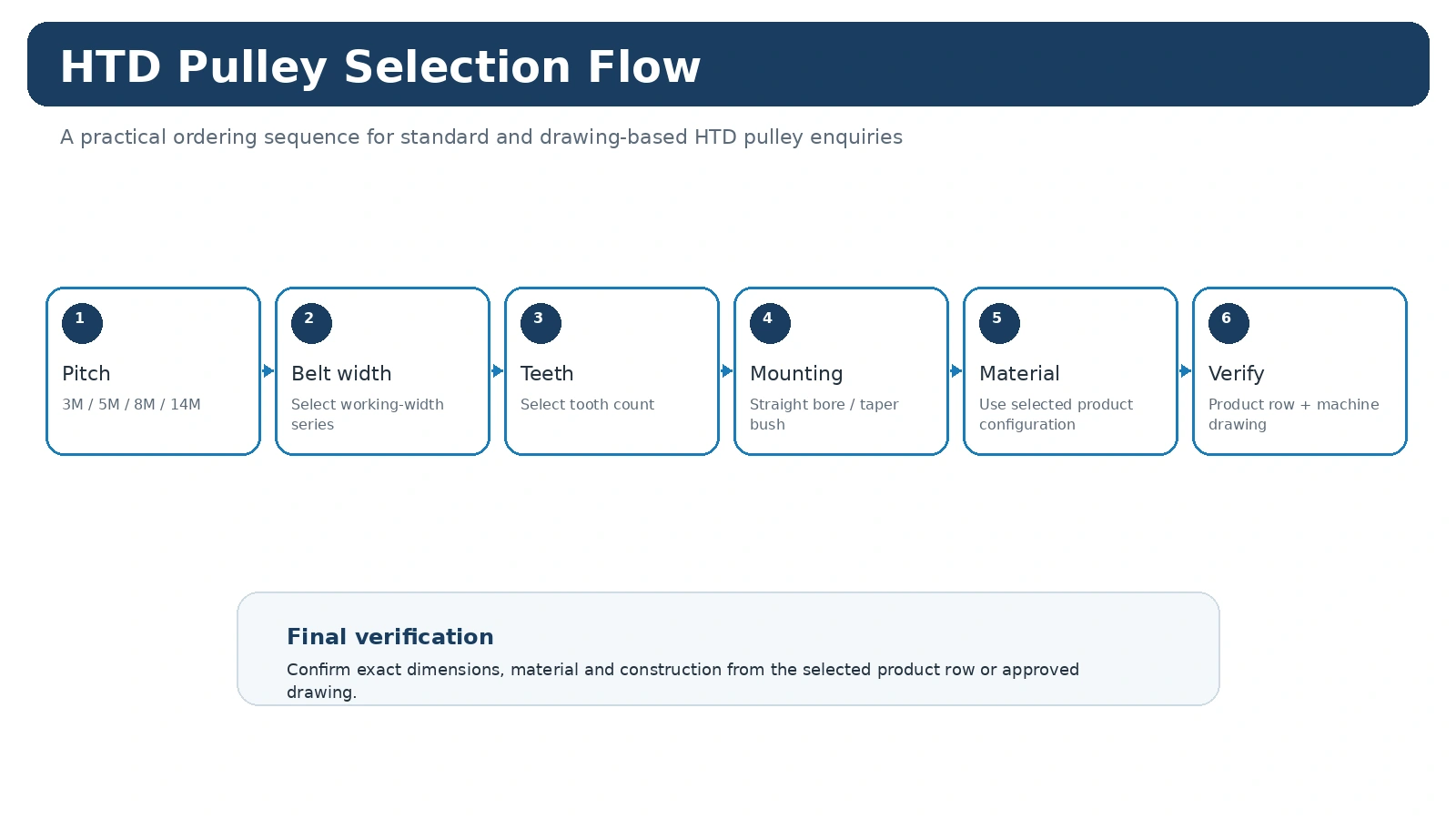
Untuk projek penggantian, bandingkan nilai yang diukur dengan susunan tali pinggang dan mesin yang dipasang sebelum memutuskan bahawa baris katalog adalah setara. Untuk projek baharu, dokumentasikan asas reka bentuk supaya pasukan penyelenggaraan kemudian dapat memahami mengapa pitch, kiraan gigi dan gaya pemasangan dipilih.
Dimensi Yang Mengawal Pemasangan
Takal boleh sepadan dengan kiraan pic dan gigi tetapi masih gagal dimuatkan pada mesin kerana kedudukan lubang, hab, bebibir atau paksi berbeza. Ukur antara muka aci, lebar tali sawat-muka, unjuran hab pada kedua-dua sisi dan garisan tali sawat relatif kepada datum mesin yang stabil. Jika sesendal tirus digunakan, catatkan kedua-dua siri takal dan kod sesendal. Jika lubang siap diperlukan, sertakan padanan, laluan kunci dan sebarang kaedah penahan pada lukisan.
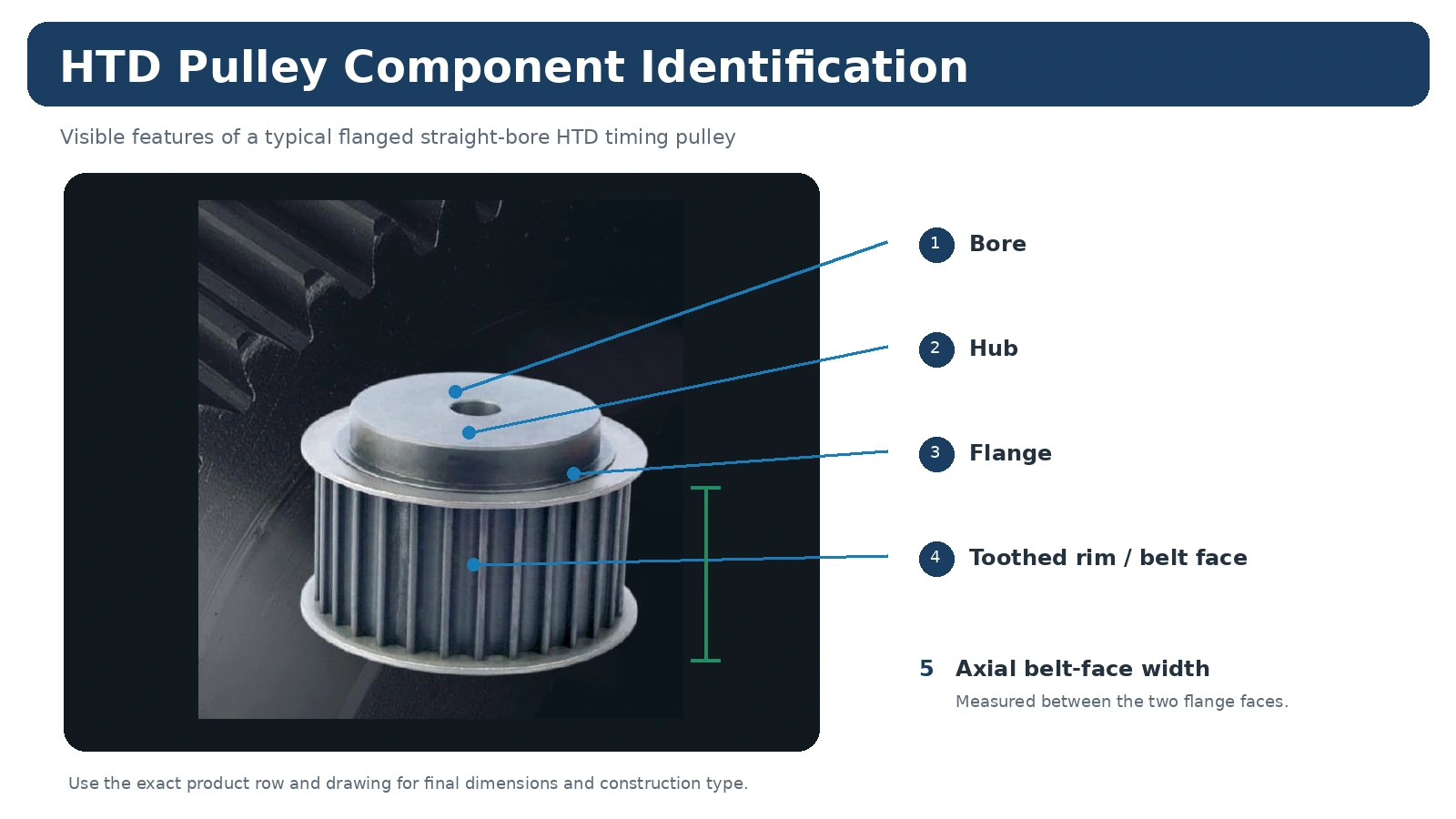
Untuk projek penggantian, bandingkan nilai yang diukur dengan susunan tali pinggang dan mesin yang dipasang sebelum memutuskan bahawa baris katalog adalah setara. Untuk projek baharu, dokumentasikan asas reka bentuk supaya pasukan penyelenggaraan kemudian dapat memahami mengapa pitch, kiraan gigi dan gaya pemasangan dipilih.
Keadaan Operasi Yang Termasuk dalam Pemilihan
Komponen pemilihan takal pemasaan sesendal tirus nominal yang sama boleh melihat servis yang sangat berbeza bergantung pada mesin. Permulaan sejam, pengunduran, pemuatan kejutan, masa operasi berterusan, suhu, pencemaran, pembersihan dan akses untuk penegangan semuanya mempengaruhi pemacu. Paksi automasi padat menekankan gerakan berulang dan penjajaran terkawal, manakala mesin penghantar atau proses mungkin menekankan akses tugas dan servis berterusan. Berikan syarat-syarat ini dan bukannya meminta takal dipilih daripada saiz sahaja.

Untuk projek penggantian, bandingkan nilai yang diukur dengan susunan tali pinggang dan mesin yang dipasang sebelum memutuskan bahawa baris katalog adalah setara. Untuk projek baharu, dokumentasikan asas reka bentuk supaya pasukan penyelenggaraan kemudian dapat memahami mengapa pitch, kiraan gigi dan gaya pemasangan dipilih.
Titik Pemeriksaan Sebelum Pemasangan
Pemeriksaan harus tertumpu pada dimensi yang mempengaruhi pemacu: antara muka aci, lokasi paksi, keadaan gigi, lebar muka dan sebarang hubungan larian atau datum yang dikawal oleh lukisan. Pernyataan kualiti generik tidak mentakrifkan penerimaan. Jika laporan dimensi, dokumen bahan atau rekod khusus pesanan diperlukan, kenal pastinya sebelum pengeluaran. Semasa penyelenggaraan, perhatikan kerosakan bebibir, haus tepi, serpihan dan tanda-tanda bahawa takal telah bergerak pada aci.
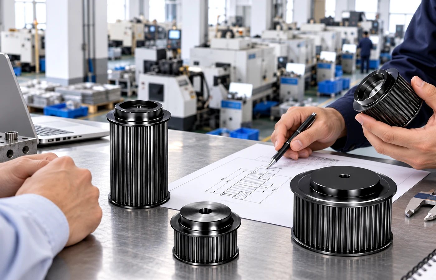
Untuk projek penggantian, bandingkan nilai yang diukur dengan susunan tali pinggang dan mesin yang dipasang sebelum memutuskan bahawa baris katalog adalah setara. Untuk projek baharu, dokumentasikan asas reka bentuk supaya pasukan penyelenggaraan kemudian dapat memahami mengapa pitch, kiraan gigi dan gaya pemasangan dipilih.
Soalan Terbuka untuk Ditutup Sebelum Memesan
Apakah profil dan lebar HTD yang tepat yang dipasang atau dinyatakan?
Apakah nisbah atau kiraan gigi sedia ada yang mesti dikekalkan?
Apakah susunan lubang, padanan, laluan kunci atau semak tirus yang diperlukan?
Berapakah unjuran hab dan kelegaan bebibir yang tersedia?
Apakah kelajuan, beban, permulaan, pengunduran dan waktu operasi?
Lukisan, bahan atau rekod pemeriksaan yang manakah mesti disertakan dengan bekalan?
Apa yang Perlu Dihantar Dengan RFQ
Hantar profil, kiraan gigi, lebar tali sawat, antara muka aci, butiran hab/flange, kuantiti, destinasi dan lakaran lukisan atau ukuran penggantian. Tambah kelajuan, nisbah, beban, jarak pusat dan persekitaran untuk pemacu baharu. Semak semula Keluarga produk HTD, gunakan panduan pemilihan, atau bandingkan yang berkaitan nota permohonan.
Pilih Takal dan Bush sebagai Sepasang
Siri takal, kiraan gigi dan penetapan bush adalah bersamaan. Sahkan kod bush yang disokong oleh baris produk tertentu dan kemudian padankan keperluan aci sebenar.
Pastikan nilai yang diukur, rujukan katalog dan keperluan projek diasingkan dengan jelas. Jika titik yang diperlukan tidak dinyatakan dalam jadual katalog yang berkaitan atau lukisan yang diluluskan, sertakannya sebagai soalan RFQ atau keperluan lukisan dan bukannya mengisi jurang dengan nilai yang munasabah tetapi tidak disahkan.
Akses Perkhidmatan Adalah Sebahagian Daripada Keputusan
Susunan semak tirus masih memerlukan ruang untuk pemasangan dan penyingkiran. Catatkan jarak pelindung dan panjang aci yang boleh diakses, terutamanya pada peralatan gantian di mana komponen berdekatan mungkin menyekat akses alat.
Rekod pembelian harus menyimpan hubungan yang jelas antara keperluan mesin dan takal yang dipilih. Ini bermakna identiti tali sawat atau profil yang lengkap, kiraan gigi, lebar kerja dan maklumat antara muka aci kekal bersama kod produk. Sebarang bahan khas, kemasan, toleransi terkawal, penandaan atau keperluan laporan harus dinyatakan secara berasingan supaya ia tidak boleh disalah anggap sebagai ciri universal seluruh keluarga.
Perolehan dan Dokumentasi
Setelah pilihan jelas, kekalkan identiti produk, kuantiti, destinasi dan semakan lukisan yang diterima pada baris pembelian yang sama. Bahagian katalog standard biasanya dirancang sekitar minimum kuantiti pengeluaran, manakala item yang lebih besar atau bernilai lebih tinggi boleh disemak berdasarkan nilai pesanan praktikal. Sampel pelanggan baharu yang layak sebanyak 1–5 keping boleh disemak pada harga sampel apabila konfigurasi dan laluan pembuatan sesuai.
Pesanan model campuran boleh disatukan ke arah nilai pesanan praktikal kira-kira USD 1,500. Bahan khas dan proses khas mengikut kuantiti minimum yang diperlukan oleh proses tersebut. Permintaan satu atau dua keping yang sangat kecil hanya dikendalikan sebagai pengesahan kejuruteraan yang layak atau kes sampel berbayar dan bukannya pesanan penggantian runcit.
Masa penghantaran disahkan selepas definisi teknikal jelas. Bahagian standard biasanya dirancang pada 10–25 hari bekerja, komponen tersuai pada 20–45 hari bekerja dan pemasangan berasaskan projek atau peralatan berkaitan pada 45–120 hari bekerja jika berkenaan. EXW, FOB, CIF dan DAP biasanya disokong; FCA, CFR, CPT, CIP dan DDP boleh dibincangkan untuk penghantaran yang sesuai. Anggap ini sebagai julat perancangan, bukan janji penghantaran sebelum semakan pesanan.
Urutan Keputusan Praktikal
Mulakan dengan kod takal, nombor bush, had maksimum lubang dan antara muka aci. Pastikan keperluan mesin berasingan daripada pilihan katalog: kenal pasti dahulu apa yang mesti dikekalkan oleh pemacu, kemudian bandingkan hanya baris atau lukisan yang sepadan dengan identiti tersebut. Ini menghalang takal yang kelihatan biasa daripada diterima sebelum antara muka fungsinya disemak.
Bagi mesin sedia ada, kekalkan hubungan asal sebelum membuat perubahan. Bagi reka bentuk baharu, catatkan nisbah sasaran, konteks operasi dan sampul pemasangan supaya pemilihan tirus boleh disemak kemudian tanpa bergantung pada ingatan atau gambar sahaja.
Bina Rekod Pengukuran
Set ukuran yang paling berguna mengandungi siri takal, kiraan gigi, nombor bush, diameter aci dan akses pemasangan. Tandakan nilai yang diukur pada mesin dan nilai yang datang daripada katalog atau lukisan yang dikeluarkan. Apabila sesuatu ciri tidak boleh diakses, gambarkan hubungannya dengan datum yang stabil dan kenal pasti ia sebagai pengesahan yang diperlukan dan bukannya mengisi jurang dengan nilai yang diandaikan.
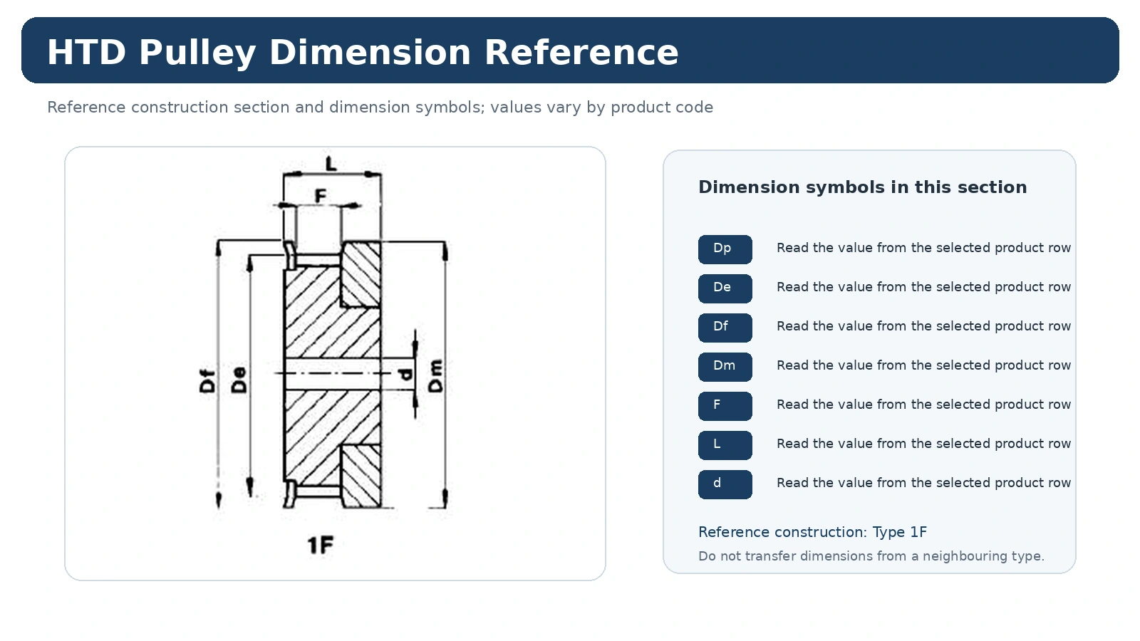
Lukisan dimensi hendaklah dilihat pada lebar penuh yang boleh dibaca. Jangan sekali-kali skala tangkapan skrin dan kemudian anggap dimensi berskala sebagai ukuran; gunakan nilai bercetak dan jenis pembinaan yang betul.
Satu Mod Kegagalan yang Patut Dielakkan
Satu kesilapan biasa ialah menganggap satu nombor bush sesuai dengan setiap kiraan gigi dalam satu siri. Ini boleh menghasilkan bahagian yang kelihatan hampir sama dalam katalog namun mengubah nisbah, garisan tali sawat, pemasangan atau akses servis. Selesaikan ciri yang bercanggah sebelum meminta harga supaya sebut harga merujuk kepada satu konfigurasi yang koheren secara mekanikal.
Jika dua konfigurasi calon masih boleh dilakukan, hantarkan kedua-dua ukuran mesin dan gambar serta pilihan yang diutamakan. Sebut harga kemudiannya boleh mengenal pasti antara muka yang masih memerlukan pengesahan dan bukannya menukar ketidakpastian kepada spesifikasi secara senyap.
Tukarkan Pilihan Teknikal Menjadi Item Baris Sedia Sebut Harga
Nyatakan keluarga HTD/profil dan maklumat tali pinggang yang lengkap.
Berikan kiraan gigi, lebar kerja dan dimensi atau rujukan lukisan yang berkaitan.
Tentukan lubang atau semak, data aci, unjuran hab dan kedudukan garisan tali sawat jika berkenaan.
Tambahkan kuantiti, destinasi, dokumen yang diperlukan dan semakan lukisan yang digunakan untuk permintaan tersebut.
Apabila satu item di atas benar-benar tidak diketahui, labelkannya untuk pengesahan. Soalan terbuka yang tepat adalah lebih berguna daripada nilai munasabah yang tidak pernah diukur.
Soalan yang Lazim Ditanya oleh Pembeli
Apa yang perlu disahkan dahulu?
Sahkan kod takal, nombor bush, had maksimum lubang dan antara muka aci. Ini menghalang dimensi kemudian daripada dibandingkan merentasi keluarga produk atau laluan pemasangan yang salah.
Maklumat apakah yang paling berguna untuk penggantian?
Hantar siri takal, kiraan gigi, nombor bush, diameter aci dan akses pemasangan, serta gambar yang jelas sebelum takal lama ditanggalkan. Gambar-gambar tersebut mengekalkan orientasi paksi dan ruang bersebelahan yang tidak dapat ditunjukkan oleh bahagian yang longgar.
Bilakah lukisan perlu digunakan?
Gunakan lukisan terkawal apabila baris katalog tidak mentakrifkan sepenuhnya antara muka aci, susunan hab/bebibir, kemasan, toleransi atau keperluan pemeriksaan yang penting kepada mesin.
Jangan Asingkan Keputusan Antara Muka Daripada Model Tepat
Ketersediaan bahan, lubang dan tirus boleh berubah mengikut saiz dan pembinaan takal. Gunakan maklumat bahan dan pemasangan yang dinyatakan untuk baris yang dipilih dan bukannya menganggap setiap ahli keluarga pitch boleh dibekalkan secara sama. Jika mesin memerlukan ciri di luar baris yang disokong, beralih kepada semakan tersuai yang dikawal lukisan.
Lubang maksimum semak tirus ialah had kapasiti untuk semak tersebut, bukan diameter aci yang tersusun. Nyatakan saiz aci sebenar. Untuk kerja lubang lurus, nyatakan antara muka siap yang diperlukan dan sebarang laluan kunci atau ciri penguncian dengan jelas. Unjuran hab dan garis tengah tali sawat hendaklah kekal kelihatan pada lukisan kerana ia boleh menentukan sama ada bahagian itu dipasang dengan betul.
Permintaan Bahan Memerlukan Sebab Fungsian
Jika terdapat beberapa bahan dalam keluarga katalog, pilih daripada konfigurasi yang sebenarnya disokong. Jika bahan, salutan atau rawatan khas diperlukan oleh persekitaran atau piawaian pelanggan, nyatakannya sebagai keperluan pesanan terkawal dan bincangkan MOQ prosesnya. Jangan simpulkan bahan hanya daripada warna gambar produk.
Untuk pemeriksaan, kenal pasti apa yang dijangka dikawal oleh pilihan bahan atau antara muka. Ini menjadikan dokumen bahan, rekod dimensi atau laporan lain bermakna kepada pesanan sebenar.
Pilih Baris Takal dan Bush sebagai Satu Sistem Pemasangan
Takal tirus-bush tidak ditentukan sepenuhnya oleh kiraan pic dan gigi HTD. Baris takal yang disokong, penetapan bush, maklumat lubang maksimum dan aci sebenar mesti disemak bersama. Bush dari saiz yang bersebelahan mungkin kelihatan serupa tetapi tergolong dalam sampul hab atau susunan pengikat yang berbeza.
Untuk penggantian penyelenggaraan, catat tanda bush sebelum pembongkaran dan catatkan dari sisi mana ia dipasang, diameter aci, keadaan laluan kunci dan ruang penyingkiran yang tersedia. Jangan gunakan andaian pandangan letupan yang dibuat secara spontan apabila katalog memberikan jenis pembinaan sebenar. Jika bush atau aci sedia ada menunjukkan fret atau kerosakan, perhatikan keadaan tersebut secara berasingan daripada pengenalpastian dimensi.
Untuk pesanan baharu, senaraikan siri takal, kiraan gigi, siri lebar, penentuan bush, aci dan kuantiti pada baris yang sama. Ini mengelakkan antara muka pemasangan daripada terpisah daripada model takal semasa sebut harga atau pembelian.
Sahkan Bush, Aci dan Ruang Penyingkiran Sebelum Pesanan Pembelian
Pemilihan semak tirus lebih mudah dikawal apabila tiga maklumat disimpan bersama: baris takal yang disokong, penetapan semak yang tepat dan aci sebenar. Tambahkan maklumat laluan kunci aci dan ruang pengeluaran yang tersedia jika ia mempengaruhi pemasangan. Lubang maksimum nominal dalam jadual bukanlah lubang siap yang dipesan; ia adalah had yang berkaitan dengan kombinasi semak/model.
Untuk penggantian, ambil gambar penanda bush dan susunan pengikat sebelum melonggarkan apa-apa. Jika pemasangan lama telah diubah suai atau tanda tidak dapat dibaca, gunakan lukisan pembinaan dan data aci yang diukur dan bukannya meneka dari diameter luar. Garisan pembelian akhir harus mengenal pasti kedua-dua takal dan bush supaya pemeriksaan yang diterima dapat memeriksa set pemasangan lengkap.
Pastikan Kod Takal, Nombor Bush dan Diameter Aci Sebenar Bersama-sama
Takal HTD tirus-bush dipilih melalui gabungan baris takal dan rujukan bush. Nombor bush boleh berubah mengikut kiraan gigi dan pembinaan, dan jadual mungkin menyatakan lubang maksimum dan bukannya diameter aci sebenar mengikut susunan. Oleh itu, pemilihan yang betul memastikan ketiga-tiga maklumat tersebut bersama-sama.
Jangan pilih bush daripada diameter aci sahaja tanpa memeriksa sama ada baris takal yang dipilih direka bentuk untuknya. Begitu juga, jangan anggap lubang maksimum sebagai spesifikasi lubang siap. Untuk penggantian, catatkan tanda bush yang kelihatan, kod takal, diameter aci dan kedudukan paksi yang dipasang sebelum pembongkaran.
Mulakan dengan pic, siri lebar dan kiraan gigi yang betul.
Gunakan nombor semak yang disenaraikan untuk baris itu, bukan andaian seluruh keluarga.
Nyatakan saiz aci sebenar dan maklumat laluan kunci pada RFQ.
Periksa kedudukan hab, akses skru dan ruang penyingkiran dalam mesin.
Jika tanda semak sedia ada tidak boleh dibaca, hantarkan dimensi aci dan gambar yang jelas daripada meneka siri tersebut. Petikan tersebut kemudiannya boleh mengenal pasti maklumat yang masih diperlukan sebelum takal dan semak dilepaskan sebagai set yang sepadan.