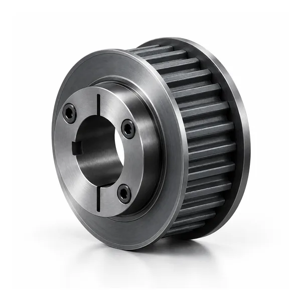
بكرة توقيت HTD 14M-40 ذات جلبة مخروطية
بكرة توقيت 14M HTD من عائلة جلبة 14M-40 المخروطية. حدد عدد الأسنان ورمز الجلبة المطابق من صف الكتالوج.
نظرة عامة على تكوين بكرة التوقيت ذات الجلبة المخروطية HTD 14M-40
بكرة توقيت 14M-40 HTD هي عائلة بكرات متزامنة ذات خطوة 14 مم، ويبلغ رقمها المرجعي الاسمي لسطح الحزام 40 في نظام تسمية الكتالوج. تُعامل هذه الصفحة السلسلة كمكون صناعي قابل للتكوين، وليس كوحدة تخزين ثابتة. يؤدي تغيير عدد الأسنان إلى تغيير قطر البكرة، وقد يؤدي أيضًا إلى تغيير المحور أو الحافة أو المادة أو تفاصيل التركيب، لذا يجب ربط الطلب بصف محدد في الكتالوج أو برسم معتمد.
عند الشراء، ابدأ بتحديد مواصفات الحزام بالكامل، وتأكد من أن الحزام المقابل يستخدم نفس المقطع العرضي HTD 14M. لا يُعدّ قياس خطوة السنّ وحده معيارًا آمنًا للتبديل بين جميع أنواع الأحزمة المنحنية. بعد التأكد من المقطع العرضي، حدد عدد الأسنان وعرض التشغيل، ثم راجع وصلة العمود، وبروز المحور، وترتيب الحواف، والمواد المتاحة. يقلل هذا التسلسل من خطأ الاستبدال الشائع المتمثل في مطابقة القطر الخارجي فقط مع إغفال نظام الأسنان أو هندسة التركيب.
يُستخدم نظام التثبيت المخروطي الموضح لهذه المجموعة لنقل الطاقة المتزامن الإيجابي. وتأتي الاستفسارات عادةً من محركات صناعية كبيرة، وآلات النسيج/الورق، وأنظمة النقل المتزامن الثقيلة. وتعتمد الملاءمة الفعلية على السرعة، والحمل المنقول، والمسافة المركزية، وبنية الحزام، والمحاذاة، والبيئة، ودعم العمود. يجب توفير هذه البيانات عند تركيب محرك جديد أو عند وجود مشاكل متكررة في تتبع الحزام أو تآكله في آلة موجودة.
واجهة البناء والعمود 14M-40
14M-40 ينتمي هذا المنتج إلى عائلة 14M HTD، وتتناول هذه الصفحة تركيب الجلبة المخروطية. يغطي جدول الكتالوج في هذه الصفحة نطاق 28-192 سنًا. تشمل رموز التصميم الظاهرة في الجدول 18F و19F و19 و20. يُرجى استخدام رمز المنتج الدقيق مع عدد الأسنان، لأن ترتيب المحور/الحافة قد يختلف ضمن سلسلة عرض واحدة.
رمز العرض 40 يُحدد هذا الدليل عائلة هذا الكتالوج، ولكنه لا يُغني عن التحقق من علامة الحزام المُطابق ورسم الأبعاد. عند استبدال الحزام، يجب الحفاظ على خط الحزام المُركّب وقياس هندسة جانب العمود قبل تحديد ما إذا كان صف الأسنان الصحيح بديلاً ميكانيكيًا.
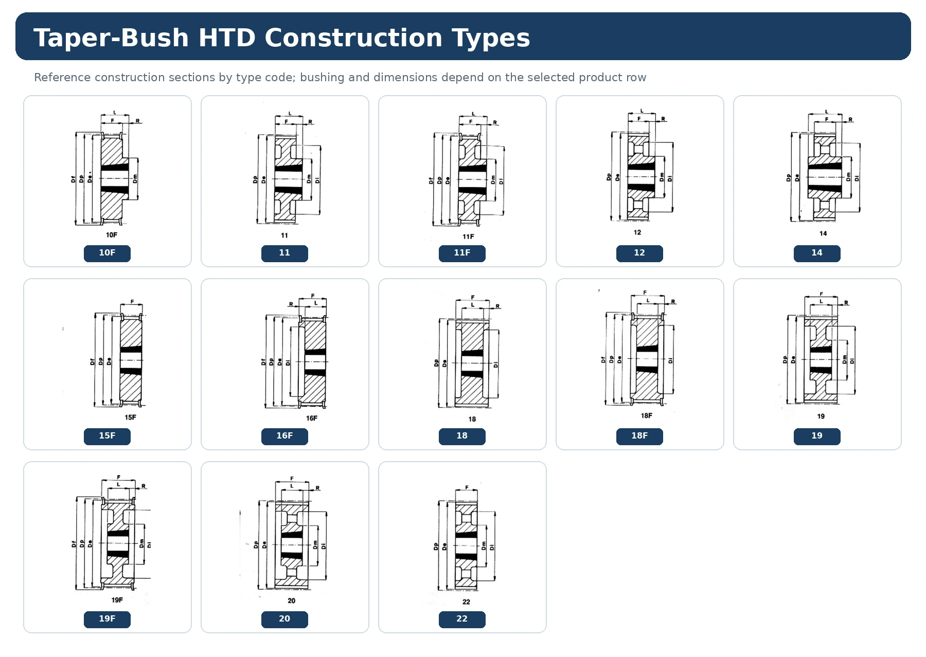
اقرأ عرض الأبعاد 14M-40 قبل الجدول
توضح طريقة عرض الأبعاد كيفية ارتباط الرموز مثل Dp و De و Df و Dm و Di و F و L والحقول المتعلقة بالثقب برسم التصميم. استخدم الرسم وصف المنتج نفسه معًا؛ ولا تنقل بُعدًا من نوع تصميم آخر لمجرد تطابق الخطوة وعدد الأسنان.
بالنسبة للطراز 14M-40، سجّل القيم التي تتحكم في التركيب - سطح العمل، وبروز المحور، ومحيط الشفة، ووصلة العمود - مقابل مرجع ثابت للآلة. إذا لم يكن قطر التجويف النهائي أو مجرى المفتاح أو التفاوت مُحددًا في صف الكتالوج، فأضفه في طلب عرض الأسعار أو الرسم المرجعي بدلًا من افتراض قيمة عامة.
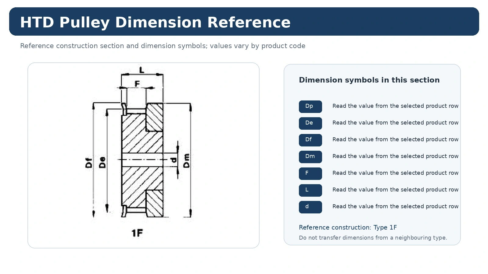
اختيار الشجيرة: يتضمن جدول 14M-40 هذا مراجع للجلب مثل 2012 و2517 و3020. يتغير مرجع الجلبة مع صف المنتج؛ تأكد من عدد الأسنان وقطر العمود بدقة بدلاً من افتراض أن جلبة واحدة تغطي السلسلة بأكملها.
جدول المواصفات الفنية 14M-40
القيم التالية مأخوذة من كتالوج بكرات التوقيت المختارة لهذه السلسلة. استخدم الرمز وعدد الأسنان معًا عند طلب عرض سعر. الأبعاد هي قيم الكتالوج؛ يجب تحديد متطلبات ملاءمة العمود النهائية، ومجرى المفتاح، وتشطيب السطح، والفحص في طلب عرض السعر أو الرسم.
| شفرة | يكتب | أسنان | شجيرة | ماكس بور | دي بي | دي | Df | Dm | دي | F | ل | R | شفة | كيلوغرام تقريبًا |
|---|---|---|---|---|---|---|---|---|---|---|---|---|---|---|
| TL 28-14M-40 | 18 فهرنهايت | 28 | 2012 | 50 | 124,78 | 122,12 | 127 | – | 94 | 54 | 32 | 11 | 400 | 2,10 |
| TL 30-14M-40 | 18 فهرنهايت | 30 | 2012 | 50 | 133,69 | 130,99 | 138 | – | 98 | 54 | 32 | 11 | 401 | 2,70 |
| TL 32-14M-40 | 18 فهرنهايت | 32 | 2012 | 50 | 142,60 | 139,88 | 154 | – | 108 | 54 | 32 | 11 | 403 | 3,40 |
| TL 34-14M-40 | 18 فهرنهايت | 34 | 2517 | 60 | 151,52 | 148,79 | 160 | – | 110 | 54 | 45 | 4,5 | 404 | 3,90 |
| TL 36-14M-40 | 18 فهرنهايت | 36 | 2517 | 60 | 160,43 | 157,68 | 168 | – | 120 | 54 | 45 | 4,5 | 405 | 4,80 |
| TL 38-14M-40 | 18 فهرنهايت | 38 | 2517 | 60 | 169,34 | 166,60 | 183 | – | 130 | 54 | 45 | 4,5 | 406 | 5,40 |
| TL 40-14M-40 | 18 فهرنهايت | 40 | 2517 | 60 | 178,25 | 175,49 | 188 | – | 138 | 54 | 45 | 4,5 | 407 | 6,00 |
| TL 44-14M-40 | 18 فهرنهايت | 44 | 3020 | 75 | 196,08 | 193,28 | 211 | – | 155 | 54 | 51 | 1,5 | 411 | – |
| TL 48-14M-40 | 18 فهرنهايت | 48 | 3020 | 75 | 213,90 | 211,11 | 226 | – | 170 | 54 | 51 | 1,5 | 412 | – |
| TL 56-14M-40 | 18 فهرنهايت | 56 | 3020 | 75 | 249,55 | 246,76 | 256 | 208 | 54 | 51 | 1,5 | 416 | – | |
| TL 64-14M-40 | 19F | 64 | 3020 | 75 | 285,21 | 282,41 | 296 | 170 | 240 | 54 | 51 | 1,5 | 418 | – |
| TL 72-14M-40 | 19 | 72 | 3020 | 75 | 320,86 | 318,06 | – | 170 | 280 | 54 | 51 | 1,5 | – | 15,00 |
| TL 80-14M-40 | 20 | 80 | 3020 | 75 | 356,51 | 353,71 | – | 170 | 315 | 54 | 51 | 1,5 | – | 16,00 |
| TL 90-14M-40 | 20 | 90 | 3020 | 75 | 401,07 | 398,28 | – | 170 | 360 | 54 | 51 | 1,5 | – | 18,00 |
| TL 112-14M-40 | 20 | 112 | 3020 | 75 | 499,11 | 496,32 | – | 170 | 457 | 54 | 51 | 1,5 | – | 25,50 |
| TL 144-14M-40 | 20 | 144 | 3020 | 75 | 641,71 | 638,92 | – | 170 | 600 | 54 | 51 | 1,5 | – | 32,00 |
| TL 168-14M-40 | 20 | 168 | 3020 | 75 | 748,66 | 745,87 | – | 170 | 706 | 54 | 51 | 1,5 | – | 43,50 |
| TL 192-14M-40 | 20 | 192 | 3020 | 75 | 855,62 | 852,82 | – | 170 | 813 | 54 | 51 | 1,5 | – | 49,50 |
أين تندرج عائلة 14M-40
يُعدّ 14M-40 جزءًا من عائلة 14M المستخدمة في محركات HTD ذات الأحجام الكبيرة، حيث تزداد أهمية محور الدوران، والشفة، ووصلة العمود، والكتلة، وسهولة الوصول للصيانة في تخطيط التركيب. ولا يُحدد مدى ملاءمة التطبيق بناءً على خطوة البكرة فقط. إذ لا يزال المحرك الجديد بحاجة إلى تحديد علاقة السرعة المطلوبة، وأساس الحمل أو عزم الدوران، والمسافة المركزية، وظروف البيئة والتشغيل قبل الانتهاء من تصميم صف البكرات.
عند استبدال الحزام، فإنّ أفضل نقطة بداية هي تحديد هوية الحزام/الملف الجانبي الحالي بالإضافة إلى عدد الأسنان الأصلي. يؤدي تغيير عدد الأسنان إلى تغيير قطر الخطوة ونسبة الدفع، بينما قد يؤدي تغيير طريقة التركيب إلى تغيير مسار الحزام أو صعوبة الوصول إلى مكان إزالته.
خيارات المواد والبناء لـ 14M-40
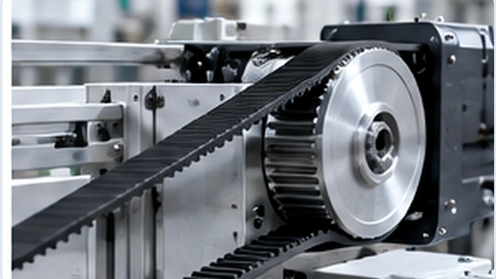
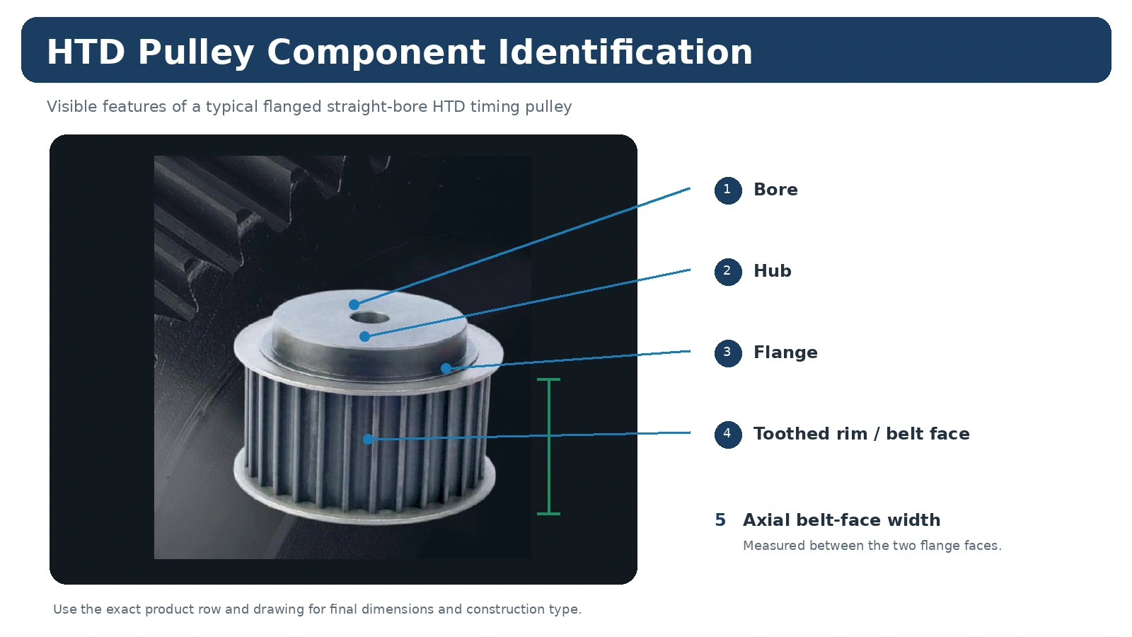
استخدم المواد والتصميم الموضحين للمنتج ذي رمز 14M-40 أو الرسم المعتمد. لا تعتمد على اللون أو مظهر السطح أو الصورة لتحديد مادة البكرة. في حال تطلب المشروع مادة أو تشطيبًا أو محورًا أو شفة أو عمودًا مختلفًا، تعامل مع ذلك كطلب خاص، وراجع تأثيره على الأبعاد والفحص قبل تقديم عرض السعر.
قد تختلف رموز التصميم ضمن نطاق 28-192 سنًا. ولهذا السبب، يجب أن يبقى رمز المنتج وعدد الأسنان وطريقة عرض التصميم معًا في سجل الطلب.
فحوصات التركيب لـ 14M-40
قبل التركيب، قارن البكرة الجديدة بالبكرة الأصلية من طراز 14M-40 أو الرسم التوضيحي. تأكد من وصلة العمود، والموضع المحوري، وحالة الشفة، ومحاذاة الحزام قبل تطبيق الشد. يجب أن يدخل الحزام في البكرة دون أن ينحرف جانبيًا بسبب عدم محاذاة العمود، أو إزاحة المحور، أو عدم صحة ترتيب الفواصل.
بعد التجميع، افحص الخصائص المهمة للآلة الفعلية، مثل التثبيت المحكم، والمحاذاة، وحرية الدوران، وتتبع السير، وأي انحراف أو وضع محوري محدد في الرسم. لا تستخدم سماحية عامة إذا كان رسم المعدات أو الطلب يحدد متطلبات مختلفة.
الطلبات والعينات والتخطيط التجاري
تُحدد الكميات الدنيا وفقًا لنوع المنتج وطريقة التصنيع وقيمة الطلب الإجمالية. وعادةً ما تتبع قطع الغيار القياسية في الكتالوج الحد الأدنى لكمية الإنتاج.
يمكن للعملاء الجدد طلب من قطعة إلى خمس قطع تجريبية عندما يكون التكوين وطريقة الإنتاج مناسبين. يتم تسعير العينات بشكل منفصل.
يمكن دمج نماذج بكرات مختلفة. وتبلغ قيمة الطلب الإجمالية حوالي 1500 دولار أمريكي، وهي القيمة المعتادة للطلبات التي تتضمن نماذج مختلطة.
قد يتم النظر في كميات من قطعة واحدة أو قطعتين فقط للتحقق الهندسي أو لمتطلبات عينة مدفوعة الأجر مؤهلة، وليس كطلبات بيع بالتجزئة؛ وبالتالي يكون سعر الوحدة أعلى.
الأجزاء القياسية: عادةً من 10 إلى 25 يوم عمل. المكونات المصممة حسب الطلب: عادةً من 20 إلى 45 يوم عمل. التجميعات أو المعدات ذات الصلة حسب المشروع: من 45 إلى 120 يوم عمل عند الاقتضاء. يتم تأكيد المدة النهائية بعد مراجعة الرسومات والمواد والكميات.
تتوفر شروط التسليم EXW وFOB وCIF وDAP بشكل شائع. ويمكن مناقشة شروط التسليم FCA وCFR وCPT وCIP وDDP للشحنات والوجهات المناسبة.
كيفية إعداد طلب عرض أسعار لـ 14M-40
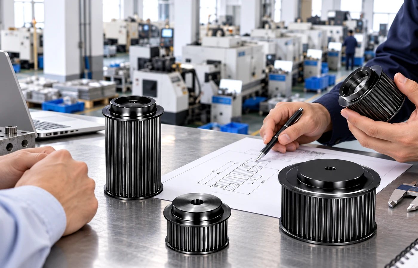
أرسل بيانات الحزام كاملةً، بما في ذلك عدد الأسنان المطلوبة، وعرض الحزام، وقطر العمود وملاءمته، وطريقة التركيب، والكمية، والوجهة. أضف رسمًا توضيحيًا بالأبعاد أو صورًا واضحة للأجزاء البديلة عندما لا تكون أبعاد محور العجلة، أو شكل الحافة، أو مجرى المفتاح، أو التشطيب، أو حدود الفحص قياسية. إذا كنت تستبدل بكرة قديمة، فأرفق قياسات الأمام والخلف والجانب بدلًا من الاعتماد على قيمة واحدة للقطر الخارجي.
للمقارنة بين القرارات ذات الصلة، انظر إلى عائلة منتجات 14 مليون، راجع دليل اختيار بكرات HTDأو انظر إرشادات التقديم لاعتبارات خاصة بالآلة.
الأسئلة الشائعة حول 14 شهرًا - 40 شهرًا
هل جميع بكرات 14M-40 قابلة للتبديل؟
لا. يُضيّق رمز السلسلة نطاق درجة الخطوة والعرض، لكن عدد الأسنان ونوع البناء والقطر الداخلي أو البطانة وأبعاد المحور وترتيب الحواف والمادة قد تختلف. تأكد من رقم الصف في الكتالوج أو الرسم التوضيحي بدقة.
هل يمكنك تقديم عرض سعر لبكرة موجودة؟
نعم، بشرط أن تكون معلومات الاستبدال كافية. أرسل بيانات علامة الحزام، وعدد الأسنان، وعرض الوجه، وتفاصيل العمود، والقياسات من كلا الجانبين. يُفضّل إرفاق رسم هندسي للأشكال غير القياسية.
هل يمكن توفير كميات صغيرة؟
قد تُؤخذ عينات صغيرة مدفوعة الأجر بعين الاعتبار للتحقق الهندسي المؤهل. ويكون مسار البيع المعتاد هو التوريد للإنتاج الصناعي بدلاً من الشراء بالتجزئة لقطعة أو قطعتين.
ما هي المستندات التي يجب طلبها مع الطلب؟
يجب على الدولة التحقق من الأبعاد المطلوبة، وتوثيق المواد، ووضع العلامات، أو سجلات الامتثال الخاصة بالطلب في مرحلة طلب عروض الأسعار حتى يمكن تأكيد التوافر والنطاق قبل الإنتاج.