How to Measure a Replacement HTD Timing Pulley should be approached as a drive-system decision. The useful starting point is the mating belt and machine interface, followed by tooth count, working width, shaft mounting and duty conditions. This guide explains the checks that help an engineer or buyer turn measure replacement timing pulley into an RFQ that can be verified against a catalogue row or drawing.
حدد نوع المحرك قبل مقارنة الأبعاد
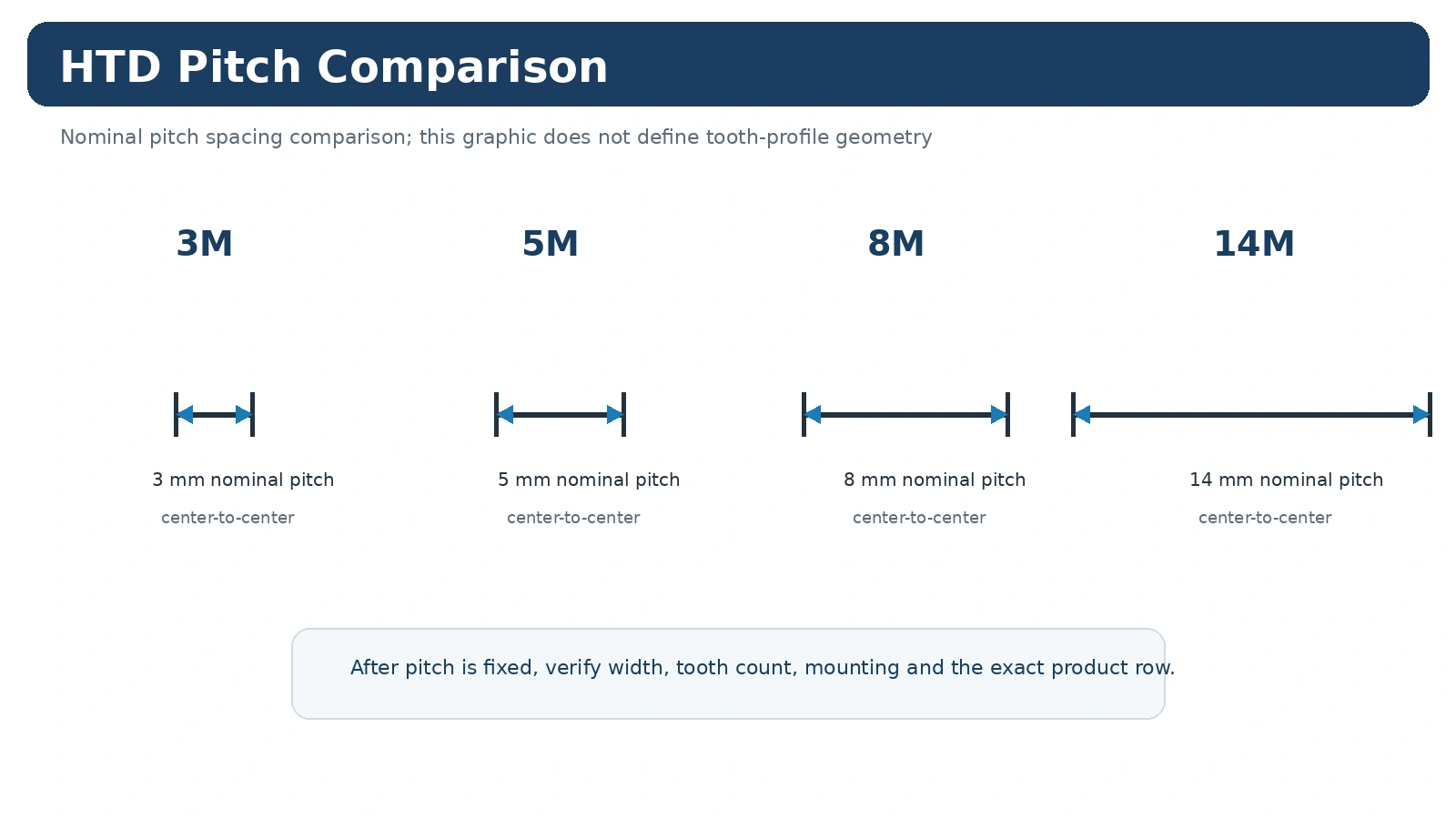
For measure replacement timing pulley, identify the complete belt marking before comparing pulley diameters. HTD is a curvilinear synchronous system and the nominal pitch must stay associated with its profile family. Record the driver and driven tooth counts when an existing ratio must be preserved. For a new drive, document the target speed ratio, driver speed and expected load before choosing tooth counts. This prevents a component-level decision from overriding the machine requirement.
في مشروع استبدال، قارن القيمة المقاسة مع الحزام المُركّب وترتيب الآلة قبل اعتبار صفّ الكتالوج مُكافئًا. أما في مشروع جديد، فوثّق أساس التصميم لكي تتمكن فرق الصيانة اللاحقة من فهم سبب اختيار درجة الميل وعدد الأسنان وطريقة التركيب.
الأبعاد التي تتحكم في عملية التركيب
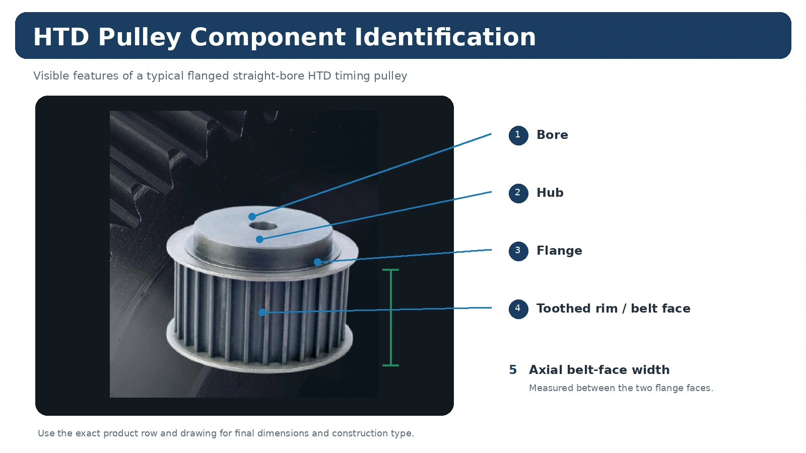
قد تتطابق البكرة مع الخطوة وعدد الأسنان، ومع ذلك قد لا تتناسب مع الآلة بسبب اختلاف التجويف أو المحور أو الحافة أو الوضع المحوري. قِسْ واجهة العمود، وعرض وجه الحزام، وبروز المحور من كلا الجانبين، وخط الحزام بالنسبة إلى مرجع ثابت للآلة. عند استخدام جلبة مخروطية، سجّل كلاً من سلسلة البكرة ورمز الجلبة. عند الحاجة إلى تجويف نهائي، أدرج التوافق ومجرى المفتاح وأي طريقة تثبيت على الرسم.
في مشروع استبدال، قارن القيمة المقاسة مع الحزام المُركّب وترتيب الآلة قبل اعتبار صفّ الكتالوج مُكافئًا. أما في مشروع جديد، فوثّق أساس التصميم لكي تتمكن فرق الصيانة اللاحقة من فهم سبب اختيار درجة الميل وعدد الأسنان وطريقة التركيب.
شروط التشغيل التي يجب مراعاتها عند الاختيار
The same nominal measure replacement timing pulley component can see very different service depending on the machine. Starts per hour, reversing, shock loading, continuous operating time, temperature, contamination, cleaning and access for tensioning all influence the drive. A compact automation axis emphasizes repeatable motion and controlled alignment, while a conveyor or process machine may emphasize continuous duty and service access. Supply these conditions instead of asking the pulley to be selected from size alone.
في مشروع استبدال، قارن القيمة المقاسة مع الحزام المُركّب وترتيب الآلة قبل اعتبار صفّ الكتالوج مُكافئًا. أما في مشروع جديد، فوثّق أساس التصميم لكي تتمكن فرق الصيانة اللاحقة من فهم سبب اختيار درجة الميل وعدد الأسنان وطريقة التركيب.
نقاط الفحص قبل التركيب
ينبغي أن يركز الفحص على الأبعاد التي تؤثر على المحرك: وصلة العمود، والموقع المحوري، وحالة الأسنان، وعرض الوجه، وأي انحراف أو علاقة مرجعية محددة في الرسم. لا يُعد بيان الجودة العام معيارًا للقبول. إذا لزم تقرير أبعاد أو وثيقة مواد أو سجل خاص بالطلب، فيُرجى تحديده قبل بدء الإنتاج. أثناء الصيانة، راقب تلف الحافة، وتآكلها، ووجود أي شوائب، وأي علامات تدل على تحرك البكرة على العمود.

في مشروع استبدال، قارن القيمة المقاسة مع الحزام المُركّب وترتيب الآلة قبل اعتبار صفّ الكتالوج مُكافئًا. أما في مشروع جديد، فوثّق أساس التصميم لكي تتمكن فرق الصيانة اللاحقة من فهم سبب اختيار درجة الميل وعدد الأسنان وطريقة التركيب.
أسئلة مفتوحة يجب إغلاقها قبل الطلب
ما هو نوع وعرض ملف تعريف HTD الذي تم تثبيته أو تحديده بالضبط؟
ما هي النسبة أو عدد الأسنان الموجودة التي يجب الحفاظ عليها؟
ما هو التجويف، أو التركيب، أو مجرى المفتاح، أو ترتيب الجلبة المخروطية المطلوب؟
ما مقدار بروز المحور وخلوص الشفة المتاح؟
ما هي السرعة، والحمل، وعدد مرات البدء، والرجوع للخلف، وساعات التشغيل؟
ما هي الرسومات أو المواد أو سجلات الفحص التي يجب أن تصاحب عملية التوريد؟
ما يجب إرساله مع طلب عرض الأسعار
أرسل بيانات المحرك، وعدد أسنانه، وعرض الحزام، ووصلة العمود، وتفاصيل المحور/الشفة، والكمية، والوجهة، ورسمًا تخطيطيًا أو رسمًا تخطيطيًا لقياسات الاستبدال. أضف السرعة، والنسبة، والحمل، والمسافة المركزية، والبيئة اللازمة للمحرك الجديد. راجع عائلات منتجات HTDاستخدم دليل الاختيارأو قارن بين ما هو ذي صلة ملاحظات التطبيق.
Measure the Drive Before the Pulley Becomes a Loose Part
The installed condition contains information that disappears after disassembly: belt-line position, hub orientation, available puller space, guard clearance and the relationship to neighboring bearings. Photograph and measure these references first.
احرص على الفصل بوضوح بين القيم المقاسة، ومراجع الكتالوج، ومتطلبات المشروع. إذا لم تُذكر نقطة مطلوبة في جدول الكتالوج ذي الصلة أو الرسم المعتمد، فأدرجها كسؤال في طلب عرض الأسعار أو كمتطلب للرسم بدلاً من ملء الفراغ بقيمة معقولة ولكن غير مُثبتة.
Build a Two-Sided Measurement Sketch
Use front and rear views plus a side profile. Record tooth count, working face, overall width, bore or bush, hub diameter and projection, flange arrangement and any readable marking. If the original belt is available, include its full designation with the sketch.
يجب أن يُوثّق سجل الشراء بوضوح العلاقة بين متطلبات الآلة والبكرة المختارة. وهذا يعني أن بيانات الحزام أو شكله، وعدد أسنانه، وعرضه، ومعلومات وصلة العمود، تبقى مُرفقة برمز المنتج. كما يجب ذكر أي متطلبات خاصة بالمواد، أو التشطيب، أو التفاوتات المُتحكّم بها، أو العلامات، أو التقارير بشكل منفصل حتى لا تُعتبر سمة عامة لجميع منتجات هذه المجموعة.
المشتريات والتوثيق
بمجرد تحديد المنتج المطلوب، احتفظ بهوية المنتج المقبولة، والكمية، والوجهة، وتعديل الرسم في نفس سطر الشراء. عادةً ما يتم تخطيط قطع الكتالوج القياسية بناءً على الحد الأدنى لكمية الإنتاج، بينما يمكن مراجعة المنتجات الأكبر حجمًا أو ذات القيمة الأعلى وفقًا لقيمة الطلب الفعلية. يمكن مراجعة عينات العملاء الجدد المؤهلة (من قطعة إلى خمس قطع) بسعر العينات عندما يكون التكوين وطريقة التصنيع مناسبين.
يمكن تجميع طلبات النماذج المختلطة لتصل قيمتها الإجمالية إلى حوالي 1500 دولار أمريكي. تخضع المواد الخاصة والعمليات الخاصة للحد الأدنى من الكمية المطلوبة لكل عملية. أما الطلبات الصغيرة جدًا المكونة من قطعة أو قطعتين، فتُعامل فقط كطلبات تحقق هندسي مؤهلة أو عينات مدفوعة الأجر، وليست طلبات استبدال بالتجزئة.
يتم تأكيد مدة التسليم بعد وضوح المواصفات الفنية. عادةً ما يتم التخطيط للأجزاء القياسية خلال 10-25 يوم عمل، والمكونات المصممة حسب الطلب خلال 20-45 يوم عمل، والتجميعات الخاصة بالمشاريع أو المعدات ذات الصلة خلال 45-120 يوم عمل عند الاقتضاء. يتم دعم شروط التسليم EXW وFOB وCIF وDAP بشكل شائع؛ ويمكن مناقشة شروط FCA وCFR وCPT وCIP وDDP للشحنات المناسبة. يرجى اعتبار هذه المدد مجرد نطاقات زمنية للتخطيط، وليست وعدًا بالتسليم قبل مراجعة الطلب.
تسلسل اتخاذ القرارات العملي
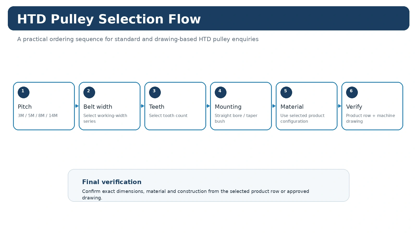
Start with tooth family, tooth count, face width, bore and hub projection. Keep the machine requirement separate from the catalogue choice: first identify what the drive must preserve, then compare only the rows or drawings that match that identity. This keeps a familiar-looking pulley from being accepted before its functional interfaces have been checked.
For an existing machine, preserve the original relationship before making changes. For a new design, record the target ratio, operating context and installation envelope so the replacement measurement set can be reviewed later without relying on memory or a photograph alone.
إنشاء سجل قياس
The most useful measurement set contains front/rear photographs, tooth count, pitch/profile, face width, bore and belt-line datum. Mark which values were measured on the machine and which values came from a catalogue or released drawing. When a feature is inaccessible, photograph its relationship to a stable datum and identify it as confirmation-required rather than filling the gap with an assumed value.
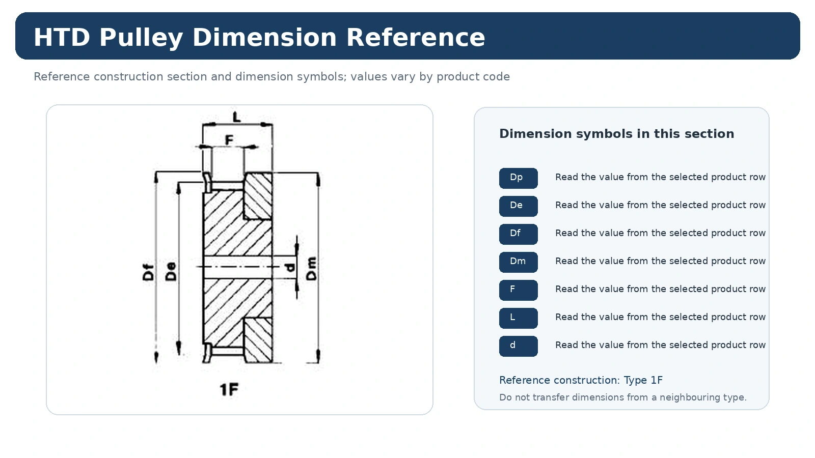
يجب عرض رسومات الأبعاد بعرضها الكامل القابل للقراءة. لا تقم أبدًا بتغيير حجم لقطة الشاشة ثم التعامل مع البعد المُغيّر كقياس؛ استخدم القيمة المطبوعة ونوع البناء الصحيح.
نمط فشل واحد يستحق تجنبه
A common error is measuring only outside diameter after the pulley has been removed. That can produce a part that appears close in the catalogue yet changes ratio, belt line, mounting or service access. Resolve the conflicting feature before requesting price so the quotation refers to one mechanically coherent configuration.
إذا بقي خياران محتملان، فأرسل قياسات الجهاز وصوره، بالإضافة إلى الخيار المفضل. وبذلك، يمكن للعرض تحديد الواجهة التي لا تزال بحاجة إلى تأكيد، بدلاً من تحويل عدم اليقين إلى مواصفات دون توضيح.
حوّل الخيار التقني إلى بند جاهز للتسعير
حدد عائلة HTD/profile وأكمل معلومات الحزام.
يرجى تقديم عدد الأسنان، وعرض العمل، والأبعاد أو الرسومات المرجعية ذات الصلة.
حدد التجويف أو الجلبة، وبيانات العمود، وبروز المحور، وموضع خط الحزام عند الاقتضاء.
أضف الكمية والوجهة والمستندات المطلوبة ورقم مراجعة الرسم المستخدم في الطلب.
عندما يكون أحد العناصر المذكورة أعلاه مجهولاً تماماً، ضع علامة عليه للتأكيد. إن طرح سؤال مفتوح دقيق أكثر فائدة من قيمة محتملة لم يتم قياسها مطلقاً.
الأسئلة الشائعة التي يطرحها المشترون
ما الذي يجب تأكيده أولاً؟
Confirm tooth family, tooth count, face width, bore and hub projection. That prevents later dimensions from being compared across the wrong product family or installation route.
ما هي المعلومات الأكثر فائدة لعملية الاستبدال؟
Send front/rear photographs, tooth count, pitch/profile, face width, bore and belt-line datum, plus clear photographs before the old pulley is removed. The photographs preserve axial orientation and neighboring clearances that a loose part cannot show.
متى يجب استخدام الرسم؟
استخدم رسمًا مُتحكمًا به كلما لم يحدد صف الكتالوج بشكل كامل واجهة العمود، أو ترتيب المحور/الشفة، أو التشطيب، أو التفاوت، أو متطلبات الفحص التي تهم الآلة.
Measure the Feature That Answers the Decision
Measurement should follow the question being solved. Tooth count and verified pitch establish the belt-side identity. Working face establishes which belt width the pulley is intended to support. Hub projection and overall axial envelope establish where the belt sits relative to the machine. Bore or bush details establish the shaft connection. Mixing these purposes is how an outside diameter or overall width gets mistaken for a catalogue selection value.
When replacing a worn part, photograph the assembly before removal and label measurements by physical feature. Do not rename them Dp, De, F or L until the catalogue drawing confirms that the measured feature corresponds to that symbol. Wear can also reduce diameters or alter edges, so the old component is a useful reference, but it is not an unquestionable nominal master.
Use the Catalogue View as a Nomenclature Map
The dimension view should be read immediately before the product table. It shows which surface a symbol refers to, while the row supplies the numeric value for that exact construction. A dash is not zero; it means the value is not stated for that row or construction.
For a custom replacement, make a simple front, rear and side sketch. Show the shaft diameter, hub projection on both sides, working face and any flange that controls the belt line. This is often more useful than a long list of unlabeled measurements.
Measure From Stable Datums Before the Old Part Leaves the Machine
The best replacement measurements are taken before disassembly, while the belt line and adjacent components still show how the pulley functions in the machine. Photograph the front, rear and side views, then record the shaft diameter, pulley face position, hub projection and available clearance from a repeatable machine datum. If spacers or shoulders are present, record their order and orientation as part of the same job record.
Measurements should be labelled by what was actually measured. Outside diameter, flange diameter, bore, overall width and hub diameter are different references; none should be silently substituted for a catalogue pitch diameter. If the existing component is worn, damaged or corroded, note that condition because the measured value may no longer represent the original manufacturing dimension.
Finally, compare the field record with the catalogue row and construction drawing. Any feature that cannot be confirmed—such as an undocumented keyway tolerance or a special hub length—should become an explicit drawing or RFQ question. This keeps uncertainty visible instead of hiding it inside an assumed replacement code.
Build the Replacement Record Before the Pulley Leaves the Machine
The easiest time to understand an old pulley is while its belt line, shaft position and neighbouring components are still visible. Before removal, photograph both faces, the belt path and any guards or spacers that establish axial location. Then record the belt marking, tooth count, working width and accessible diameters using a stable measurement datum.
Once the pulley is loose on a bench, orientation and installed spacing can be difficult to reconstruct. Wear can also make an old diameter smaller than the nominal value, so field measurements should be compared with the correct catalogue symbols instead of copied directly into a new drawing. If a feature cannot be measured accurately, mark it as a point to confirm.
Photograph front, rear, belt line and neighbouring clearances.
Record belt marking, tooth count, width series and any readable pulley code.
Measure bore or bush, hub projection, total width and relevant diameters.
Note wear, movement, fretting, flange contact or damaged teeth that may explain the replacement.
Send the measurement sheet together with photographs. A supplier can then compare the installed part with the appropriate model row and construction view. This is safer than requesting “same as sample” when the sample may already be worn or modified.