Timing Pulley Dimensions Dp, De, Df, Dm, Di, F and L Explained should be approached as a drive-system decision. The useful starting point is the mating belt and machine interface, followed by tooth count, working width, shaft mounting and duty conditions. This guide explains the checks that help an engineer or buyer turn timing pulley dimensions into an RFQ that can be verified against a catalogue row or drawing.
Визначте диск перед порівнянням розмірів
For timing pulley dimensions, identify the complete belt marking before comparing pulley diameters. HTD is a curvilinear synchronous system and the nominal pitch must stay associated with its profile family. Record the driver and driven tooth counts when an existing ratio must be preserved. For a new drive, document the target speed ratio, driver speed and expected load before choosing tooth counts. This prevents a component-level decision from overriding the machine requirement.
Для проекту заміни порівняйте виміряне значення з встановленим ременем та розташуванням машини, перш ніж вирішити, чи рядок каталогу еквівалентний. Для нового проекту задокументуйте основу проектування, щоб згодом команди з обслуговування могли зрозуміти, чому було обрано крок, кількість зубців та стиль кріплення.
Розміри, що контролюють встановлення
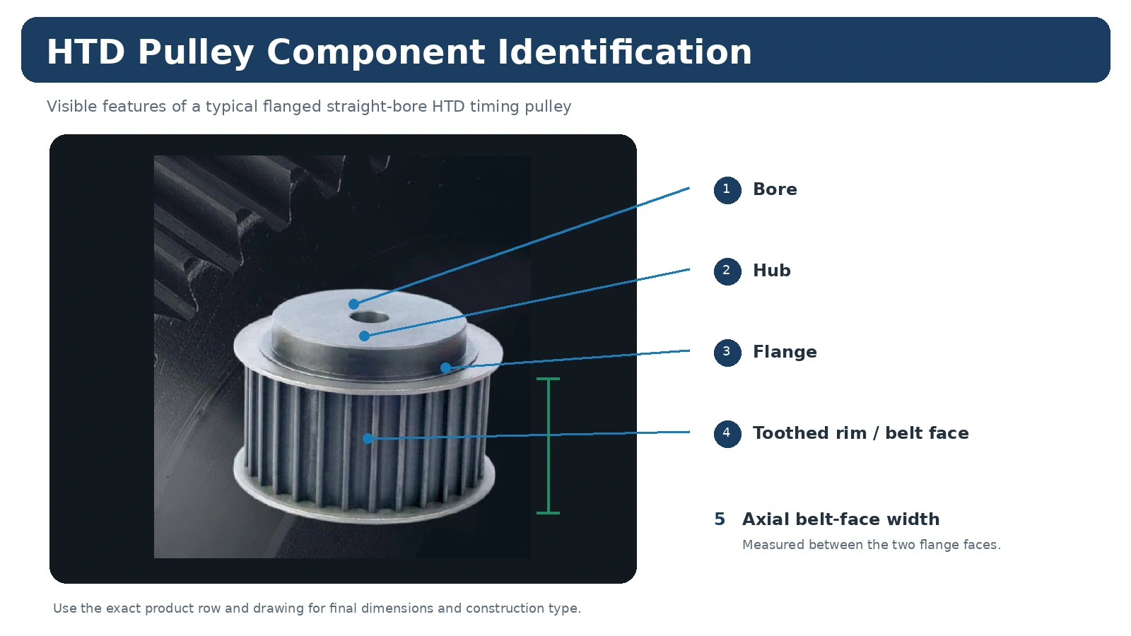
Шків може мати однаковий крок та кількість зубців, але все одно не підходити до машини через різне положення отвору, маточини, фланця або осьового положення. Виміряйте з'єднання вала, ширину поверхні ременя, виступ маточини з обох боків та лінію ременя відносно стабільної точки опори машини. Якщо використовується конічна втулка, запишіть як серію шківа, так і код втулки. Якщо потрібен готовий отвір, вкажіть на кресленні посадку, шпонкову канавку та будь-який спосіб кріплення.
Для проекту заміни порівняйте виміряне значення з встановленим ременем та розташуванням машини, перш ніж вирішити, чи рядок каталогу еквівалентний. Для нового проекту задокументуйте основу проектування, щоб згодом команди з обслуговування могли зрозуміти, чому було обрано крок, кількість зубців та стиль кріплення.
Умови експлуатації, що входять до вибору
The same nominal timing pulley dimensions component can see very different service depending on the machine. Starts per hour, reversing, shock loading, continuous operating time, temperature, contamination, cleaning and access for tensioning all influence the drive. A compact automation axis emphasizes repeatable motion and controlled alignment, while a conveyor or process machine may emphasize continuous duty and service access. Supply these conditions instead of asking the pulley to be selected from size alone.

Для проекту заміни порівняйте виміряне значення з встановленим ременем та розташуванням машини, перш ніж вирішити, чи рядок каталогу еквівалентний. Для нового проекту задокументуйте основу проектування, щоб згодом команди з обслуговування могли зрозуміти, чому було обрано крок, кількість зубців та стиль кріплення.
Точки огляду перед встановленням
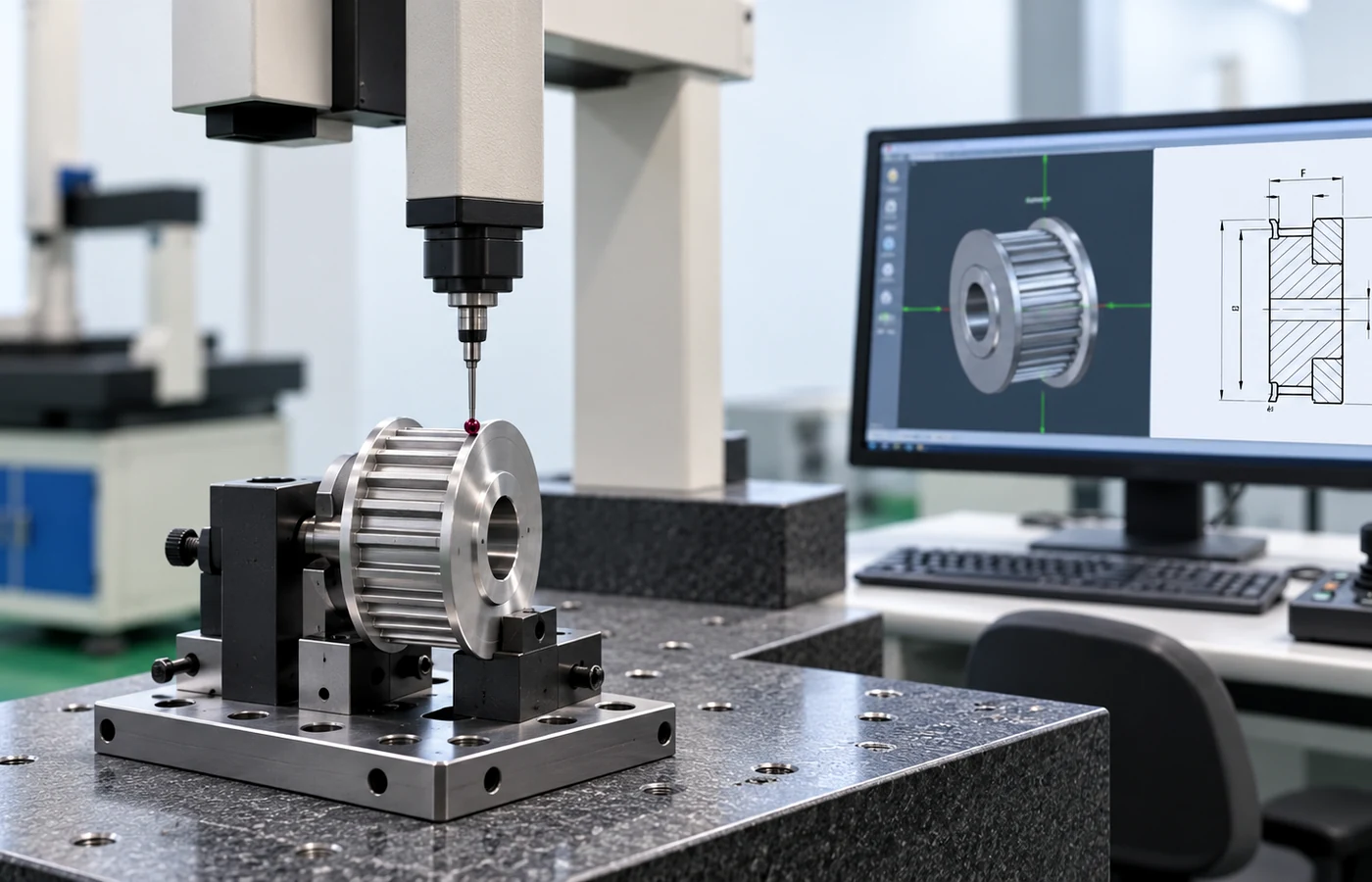
Перевірка повинна бути зосереджена на розмірах, що впливають на привід: з'єднання вала, осьове розташування, стан зуба, ширина торця та будь-яке биття або зв'язок з базами, контрольовані кресленням. Загальна декларація якості не визначає приймання. Якщо потрібен звіт про розміри, документація щодо матеріалів або запис для конкретного замовлення, ідентифікуйте його перед початком виробництва. Під час технічного обслуговування слідкуйте за пошкодженням фланців, зносом кромок, сміттям та ознаками того, що шків рухався на валу.
Для проекту заміни порівняйте виміряне значення з встановленим ременем та розташуванням машини, перш ніж вирішити, чи рядок каталогу еквівалентний. Для нового проекту задокументуйте основу проектування, щоб згодом команди з обслуговування могли зрозуміти, чому було обрано крок, кількість зубців та стиль кріплення.
Відкриті питання, які потрібно закрити перед замовленням
Який саме HTD-профіль та ширина встановлено або зазначено?
Яке співвідношення або існуючу кількість зубів необхідно зберегти?
Який отвір, посадка, шпонкова канавка або конічна втулка потрібні?
Який виступ маточини та зазор фланця доступний?
Які швидкість, навантаження, кількість пусків, реверс та години роботи?
Які креслення, матеріали або записи про перевірку повинні супроводжувати постачання?
Що надсилати разом із запитом цінової пропозиції
Надішліть профіль, кількість зубців, ширину ременя, інтерфейс вала, деталі маточини/фланця, кількість, місце призначення та креслення або ескіз вимірювань для заміни. Додайте швидкість, передавальне число, навантаження, міжосьову відстань та середовище для нового приводу. Перегляньте Сімейства продуктів HTD, використовуйте посібник з виборуабо порівняйте відповідні нотатки щодо застосування.
Dimension Symbols Need the Correct Construction View
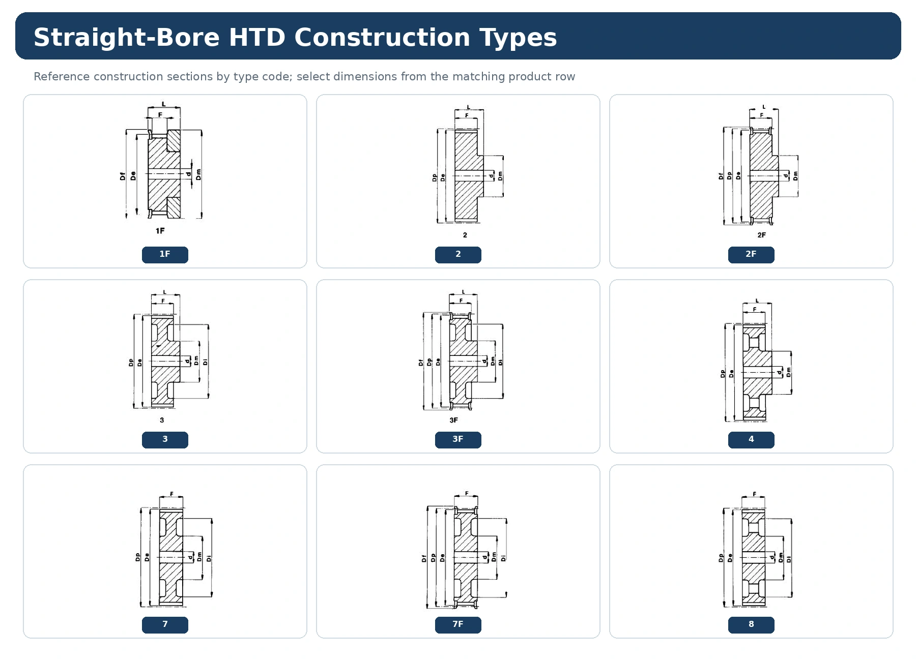
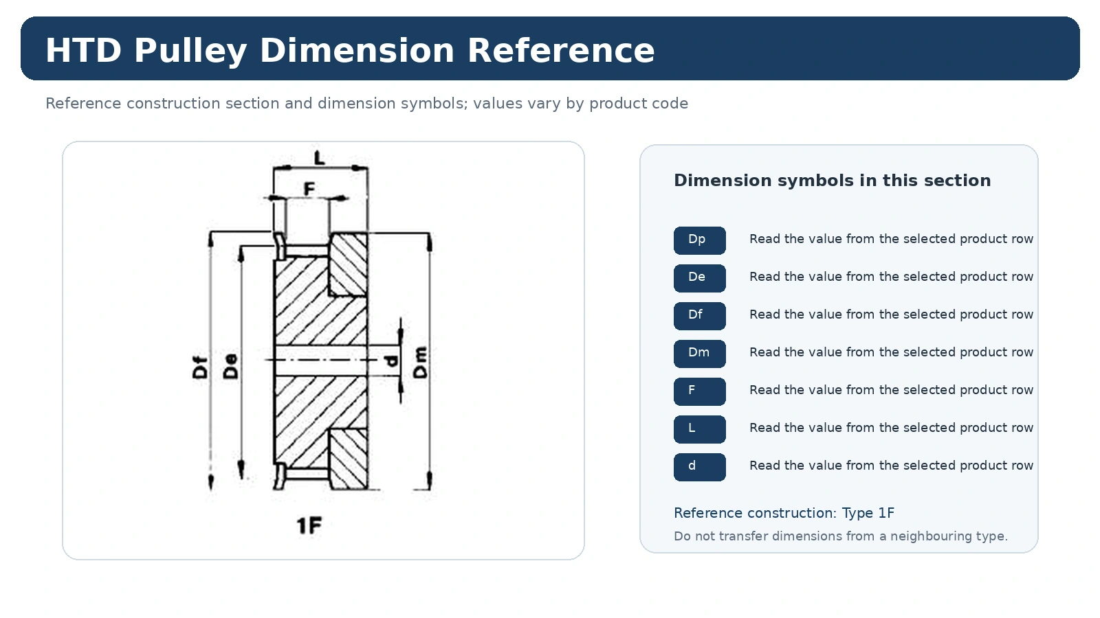
Symbols such as Dp, De, Df, Dm, Di, F, L and d only become useful when they are read on the construction view associated with the model. Do not transfer a letter value from one construction type to another simply because the outside form looks similar.
Чітко розділяйте виміряні значення, посилання на каталог та вимоги до проекту. Якщо необхідний пункт не зазначено у відповідній таблиці каталогу або затвердженому кресленні, включіть його як запитання до запиту цінових пропозицій або вимогу до креслення, замість того, щоб заповнювати прогалину правдоподібним, але неперевіреним значенням.
Use Field Measurements as Cross-Checks
A measured outside diameter or overall width can help identify a replacement, but it should be recorded as a field measurement rather than silently relabeled as a catalogue symbol. This keeps the comparison traceable when a measured value and a catalogue reference differ.
У записі про закупівлю має бути чітко зазначено зв'язок між вимогами до машини та обраним шківом. Це означає, що повна інформація про ідентичність ременя або профілю, кількість зубців, робочу ширину та з'єднання вала зберігається разом із кодом виробу. Будь-які спеціальні вимоги до матеріалу, обробки, контрольованого допуску, маркування або звіту слід вказувати окремо, щоб їх не можна було сплутати з універсальною характеристикою всієї лінійки.
Закупівлі та документація
Після того, як вибір буде чітким, збережіть прийнятий ідентифікатор продукту, кількість, місце призначення та редакцію креслення в одному рядку закупівлі. Стандартні каталожні деталі зазвичай плануються з урахуванням мінімальних обсягів виробництва, тоді як більші або дорогі товари можуть бути перевірені на відповідність практичній вартості замовлення. Кваліфіковані зразки нових клієнтів обсягом від 1 до 5 штук можуть бути перевірені за зразковою ціною, якщо конфігурація та виробничий маршрут підходять.
Замовлення на змішані моделі можуть бути об'єднані до практичної вартості замовлення близько 1500 доларів США. Спеціальні матеріали та спеціальні процеси відповідають мінімальній кількості, необхідної для цього процесу. Дуже невеликі запити на одну або дві деталі обробляються лише як кваліфікована інженерна перевірка або випадки платних зразків, а не як роздрібні замовлення на заміну.
Термін виконання підтверджується після чіткого технічного визначення. Стандартні деталі зазвичай плануються протягом 10–25 робочих днів, компоненти на замовлення – протягом 20–45 робочих днів, а проектні вузли або супутнє обладнання – протягом 45–120 робочих днів, де це можливо. Зазвичай підтримуються умови EXW, FOB, CIF та DAP; для відповідних поставок можна обговорити умови FCA, CFR, CPT, CIP та DDP. Розглядайте їх як планові діапазони, а не як обіцянку щодо відвантаження перед переглядом замовлення.
Практична послідовність рішень
Start with the exact construction view and its Dp, De, Df, Dm, Di, F, L and bore references. Keep the machine requirement separate from the catalogue choice: first identify what the drive must preserve, then compare only the rows or drawings that match that identity. This keeps a familiar-looking pulley from being accepted before its functional interfaces have been checked.
For an existing machine, preserve the original relationship before making changes. For a new design, record the target ratio, operating context and installation envelope so the dimension interpretation can be reviewed later without relying on memory or a photograph alone.
Створіть запис вимірювань
The most useful measurement set contains catalogue code, construction type and the matching dimension row. Mark which values were measured on the machine and which values came from a catalogue or released drawing. When a feature is inaccessible, photograph its relationship to a stable datum and identify it as confirmation-required rather than filling the gap with an assumed value.
Креслення з розмірами слід переглядати з повною шириною, яку можна читати. Ніколи не масштабуйте знімок екрана, а потім не сприймайте масштабований розмір як вимірювання; використовуйте надруковане значення та правильний тип конструкції.
Один режим невдачі, якого варто уникати
A common error is reading a dimension symbol from the wrong construction type. That can produce a part that appears close in the catalogue yet changes ratio, belt line, mounting or service access. Resolve the conflicting feature before requesting price so the quotation refers to one mechanically coherent configuration.
Якщо залишаються два можливих варіанти конфігурацій, надішліть як вимірювання та фотографії машини, так і бажаний варіант. Кошторис тоді може визначити, який інтерфейс все ще потребує підтвердження, замість того, щоб мовчки перетворювати невизначеність на специфікацію.
Перетворіть технічний вибір на готовий до складання комерційної пропозиції рядок
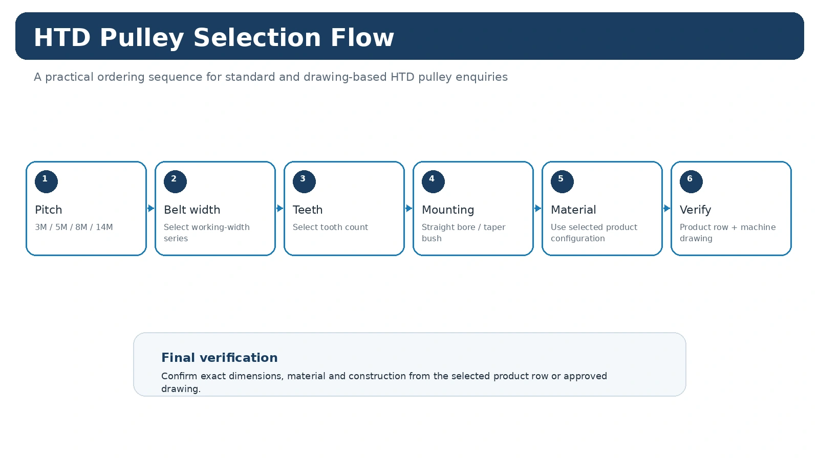
Вкажіть сімейство HTD/профілів та повну інформацію про ремінь.
Вкажіть кількість зубців, робочу ширину та відповідні розміри або посилання на креслення.
Визначте отвір або втулку, дані вала, виступ маточини та положення лінії ременя, де це можливо.
Додайте кількість, місце призначення, необхідні документи та версію креслення, використану для запиту.
Коли один із вищезазначених пунктів справді невідомий, позначте його для підтвердження. Точне відкрите питання корисніше, ніж правдоподібне значення, яке ніколи не вимірювалося.
Питання, які покупці часто ставлять
Що слід підтвердити в першу чергу?
Confirm the exact construction view and its Dp, De, Df, Dm, Di, F, L and bore references. That prevents later dimensions from being compared across the wrong product family or installation route.
Яка інформація найкорисніша для заміни?
Send catalogue code, construction type and the matching dimension row, plus clear photographs before the old pulley is removed. The photographs preserve axial orientation and neighboring clearances that a loose part cannot show.
Коли слід використовувати малюнок?
Використовуйте контрольоване креслення щоразу, коли рядок каталогу не повністю визначає з'єднання вала, розташування маточини/фланця, обробку, допуск або вимоги до контролю, що мають значення для машини.
Measure the Feature That Answers the Decision
Measurement should follow the question being solved. Tooth count and verified pitch establish the belt-side identity. Working face establishes which belt width the pulley is intended to support. Hub projection and overall axial envelope establish where the belt sits relative to the machine. Bore or bush details establish the shaft connection. Mixing these purposes is how an outside diameter or overall width gets mistaken for a catalogue selection value.
When replacing a worn part, photograph the assembly before removal and label measurements by physical feature. Do not rename them Dp, De, F or L until the catalogue drawing confirms that the measured feature corresponds to that symbol. Wear can also reduce diameters or alter edges, so the old component is a useful reference, but it is not an unquestionable nominal master.
Use the Catalogue View as a Nomenclature Map
The dimension view should be read immediately before the product table. It shows which surface a symbol refers to, while the row supplies the numeric value for that exact construction. A dash is not zero; it means the value is not stated for that row or construction.
For a custom replacement, make a simple front, rear and side sketch. Show the shaft diameter, hub projection on both sides, working face and any flange that controls the belt line. This is often more useful than a long list of unlabeled measurements.
Keep Each Diameter and Axial Dimension Attached to Its Drawing Symbol
Dimension symbols are useful only when the reference surface is clear. Dp, De, Df, Dm, Di, F and L can refer to different functional or envelope dimensions in the selected catalogue, and their relationship depends on the construction type being viewed. Copying a value without its row and drawing can therefore create an apparent match that fails at the hub, flange or guard.
During replacement measurement, distinguish catalogue dimensions from field dimensions. A caliper can measure an accessible outside surface, but that reading should not be relabelled as pitch diameter unless the catalogue defines and derives it that way. Record the physical surface that was measured, then use the correct product row to compare it with the published symbol.
For purchasing, put the dimensions that actually control the installation on the drawing or RFQ: shaft connection, axial location, working face and any critical envelope limit. Other catalogue values can remain reference data. This keeps the order focused on the interfaces that determine whether the pulley will fit and run in the intended belt plane.
Use Dimension Symbols as a Map to the Correct Construction View
Symbols such as Dp, De, Df, Dm, Di, F, L and d only become useful when they are read on the correct drawing and product row. A symbol name does not guarantee that every construction type has the same physical feature, and a dash in a table should not be replaced by a value taken from another type.
For replacements, compare the catalogue value with a real machine measurement only after confirming that both refer to the same feature. Do not scale a PDF or screenshot and treat the on-screen size as a dimension. Use printed values, the selected construction code and an actual measurement of the installed pulley when a fit must be confirmed.
Use Dp as the pitch-diameter reference where the selected drawing defines it.
Keep outside and flange diameter symbols separate when both are present.
Read F, L and hub-related dimensions from the same construction type.
Use bore or bush fields from the selected row; add special fits on the drawing.
When preparing an RFQ, include the product code and the dimensions that control installation rather than copying an entire table without context. This reduces the risk that purchasing selects a row with the correct diameter but the wrong hub or shaft interface.