HTD 14M-170 Taper Bush Timing Pulley
14M-170 конус тәрізді втулка тұқымдасына жататын 14M HTD уақыт шкиві. Каталог қатарынан тістер санын және сәйкес втулка кодын таңдаңыз.
HTD 14M-170 Taper Bush Timing Pulley Configuration Overview
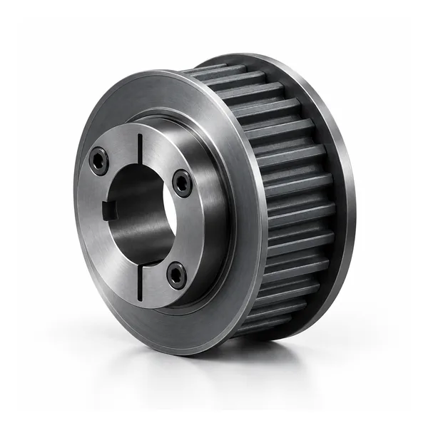
14M-170 HTD Timing Pulley is a 14 mm pitch synchronous pulley family with a nominal belt-face reference of 170 in the catalogue naming system. This page treats the series as a configurable industrial component rather than a single fixed SKU. Tooth count changes pulley diameter and may also change hub, flange, material or mounting details, so the order must be tied to a specific catalogue row or an approved drawing.
For procurement, begin with the complete belt designation and confirm that the mating belt uses the same HTD 14M profile. Pitch alone is not a safe interchange rule for every curvilinear belt family. After profile confirmation, select tooth count and working width, then review the shaft interface, hub projection, flange arrangement and available material. This sequence reduces the common replacement error of matching only outside diameter while overlooking the tooth system or mounting geometry.
The taper-bush mounting shown for this family is intended for positive synchronous power transmission. Typical enquiries come from larger industrial drives, textile/paper machinery and heavy synchronous transmission. Actual suitability depends on speed, transmitted load, center distance, belt construction, alignment, environment and shaft support. Those duty inputs should be supplied for a new drive or when an existing machine has recurring belt-tracking or wear problems.
14M-170 Construction and Shaft Interface
14M-170 belongs to the 14M HTD family and this page covers taper-bush mounting. The catalogue table on this page spans 38–216 teeth. Construction codes visible in the table include 4F, 9W, 9A. Use the exact product code with the tooth count because the hub/flange arrangement can change inside one width series.
The width code 170 identifies this catalogue family; it is not a substitute for checking the mating belt marking and the dimension drawing. For replacement work, preserve the installed belt line and measure the shaft-side geometry before deciding that a row with the correct teeth is a mechanical substitute.
Read the 14M-170 Dimension View Before the Table
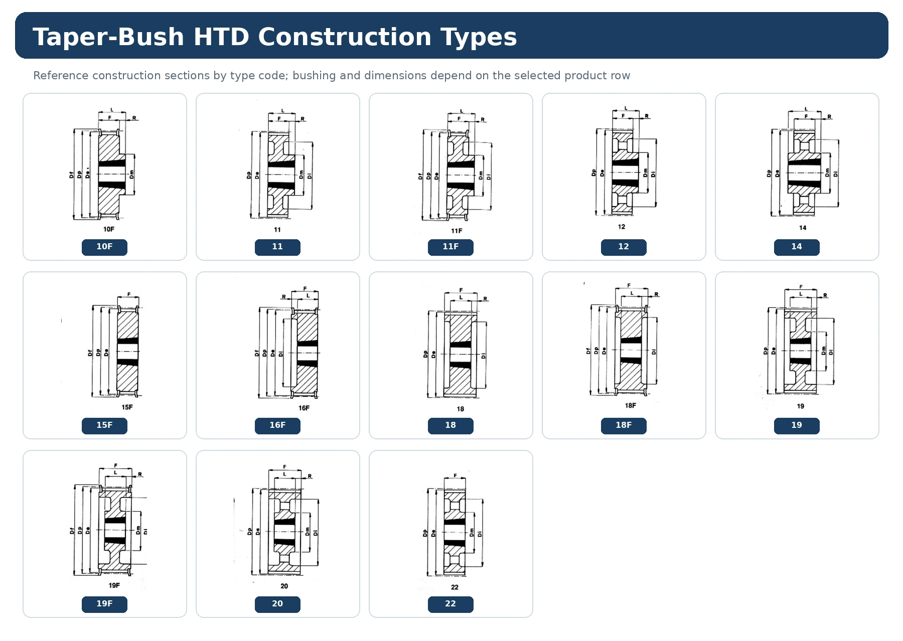
The dimension view explains how symbols such as Dp, De, Df, Dm, Di, F, L and bore-related fields relate to the construction drawing. Use the drawing and the same product row together; do not transfer a dimension from another construction type simply because the pitch and tooth count match.
For 14M-170, record the values that control installation—working face, hub projection, flange envelope and shaft connection—against a stable machine datum. If a finished bore, keyway or tolerance is not defined by the catalogue row, add it on the RFQ or controlled drawing instead of assuming a universal value.
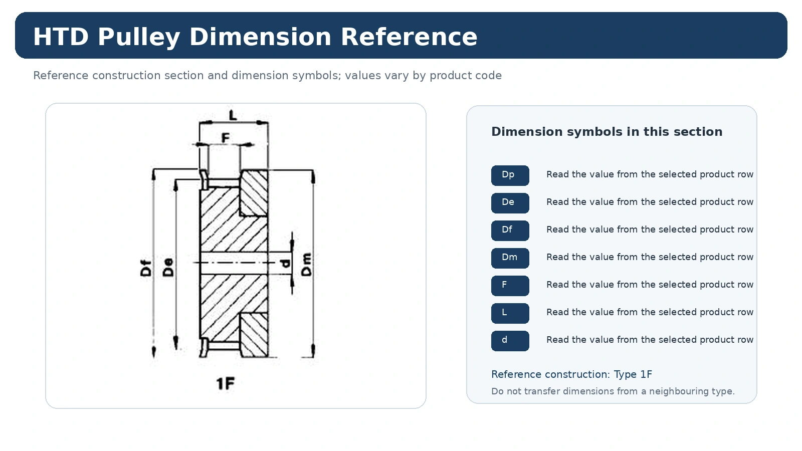
Bush selection: this 14M-170 table includes bush references such as 3030, 3535, 4040, 5050. The bush reference changes with the product row; confirm the exact tooth count and shaft diameter rather than assuming one bush covers the whole series.
14M-170 Technical Specification Table
The following values are transcribed from the selected timing-pulley catalogue for this series. Use the code and tooth count together when requesting a quotation. Dimensions are catalogue values; final shaft fit, keyway, surface finish and inspection requirements should be stated on the RFQ or drawing.
| Code | Type | Teeth | Bush | Max Bore | Dp | De | Df | Dm | Di | F | L | R | Flange | Approx. kg |
|---|---|---|---|---|---|---|---|---|---|---|---|---|---|---|
| 38-14M-170 | 4F | 38 | 3030 | 75 | 169,34 | 166,60 | 183,0 | – | 130 | 187 | 76 | 55,5 | FL172 | 11,70 |
| 40-14M-170 | 4F | 40 | 3030 | 75 | 178,25 | 175,49 | 188,0 | – | 138 | 187 | 76 | 55,5 | FL162 | 13,00 |
| 44-14M-170 | 4F | 44 | 3535 | 90 | 196,08 | 193,28 | 211,0 | – | 153 | 187 | 89 | 49,0 | FL175 | 15,00 |
| 48-14M-170 | 4F | 48 | 3535 | 90 | 213,90 | 211,11 | 226,0 | – | 170 | 187 | 89 | 49,0 | FL180 | 19,00 |
| 56-14M-170 | 4F | 56 | 3535 | 90 | 249,55 | 246,76 | 256,0 | – | 208 | 187 | 89 | 49,0 | FL182 | 28,50 |
| 64-14M-170 | 4F | 64 | 4040 | 100 | 285,21 | 282,41 | 296,0 | – | 240 | 187 | 102 | 42,5 | FL184 | 41,00 |
| 72-14M-170 | 9W | 72 | 4040 | 100 | 320,86 | 318,06 | – | 230 | 280 | 187 | 102 | 42,5 | – | 46,90 |
| 80-14M-170 | 9W | 80 | 4040 | 100 | 356,51 | 353,71 | – | 230 | 315 | 187 | 102 | 42,5 | – | 48,00 |
| 90-14M-170 | 9A | 90 | 4040 | 100 | 401,07 | 398,28 | – | 230 | 360 | 187 | 102 | 42,5 | – | 52,50 |
| 112-14M-170 | 9A | 112 | 5050 | 125 | 499,11 | 496,32 | – | 265 | 457 | 187 | 127 | 30,0 | – | 74,50 |
| 144-14M-170 | 9A | 144 | 5050 | 125 | 641,71 | 638,92 | – | 265 | 600 | 187 | 127 | 30,0 | – | 91,00 |
| 168-14M-170 | 9A | 168 | 5050 | 125 | 748,66 | 745,87 | – | 265 | 706 | 187 | 127 | 30,0 | – | 116,00 |
| 192-14M-170 | 9A | 192 | 5050 | 125 | 855,62 | 852,82 | – | 265 | 813 | 187 | 127 | 30,0 | – | 134,00 |
| 216-14M-170 | 9A | 216 | 5050 | 125 | 962,57 | 959,76 | – | 265 | 920 | 187 | 127 | 30,0 | – | 146,50 |
Where the 14M-170 Family Fits
14M-170 is part of the 14M family used for larger HTD drive envelopes where hub, flange, shaft interface, mass and service access become increasingly important to installation planning. Application suitability is not determined by pitch alone. A new drive still needs the required speed relationship, load or torque basis, center distance, environment and service conditions before the pulley row can be finalized.
For a replacement, the safest starting point is the existing belt/profile identity plus the original tooth count. Changing the tooth count changes pitch diameter and drive ratio, while changing the mounting construction can move the belt line or alter removal access.
Material and Construction Choices for 14M-170
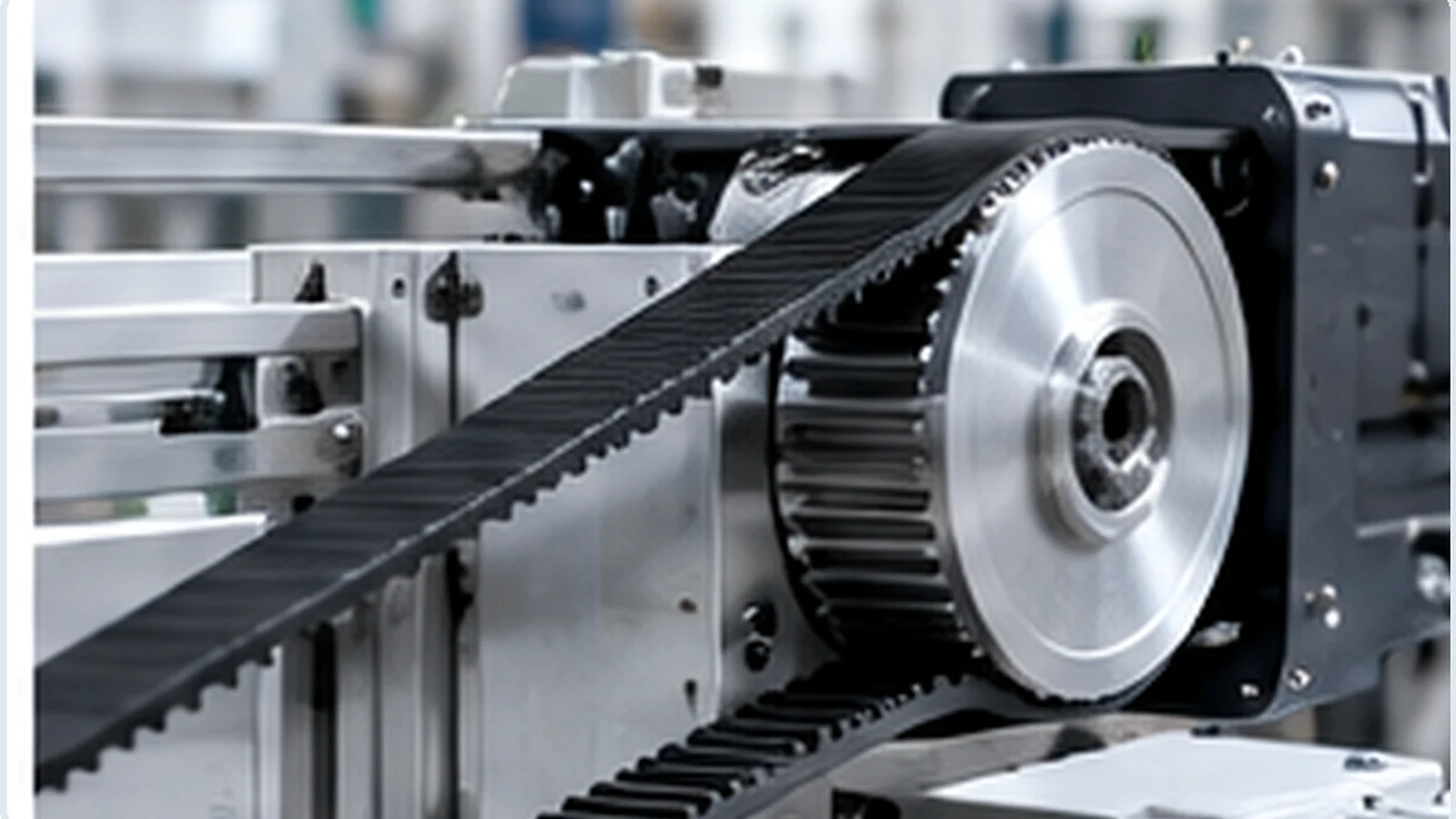
Use the material and construction shown for the exact 14M-170 product code or approved drawing. Do not identify pulley material from color, surface appearance or a photograph. Where a project requests a different material, finish, hub, flange or shaft feature, treat that as a custom requirement and review its effect on dimensions and inspection before quotation.
Within the 38–216 teeth range, construction codes can vary. That variation is why the product code, tooth count and construction view should remain together in the order record.
Installation Checks for 14M-170
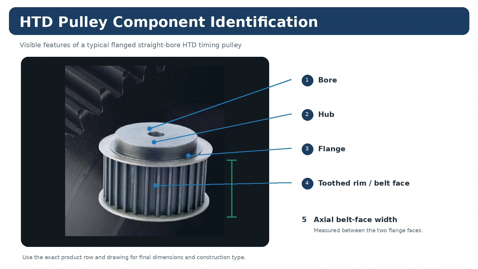
Before installation, compare the new pulley with the released 14M-170 row or drawing. Verify the shaft connection, axial position, flange condition and belt line before tension is applied. The belt should enter the pulley without being forced sideways by a misaligned shaft, displaced hub or incorrect spacer arrangement.
After assembly, inspect the characteristics that matter to the actual machine—secure mounting, alignment, free rotation, belt tracking and any drawing-controlled runout or axial position. Do not apply a generic tolerance where the equipment or order drawing defines a different requirement.
Ordering, Samples and Commercial Planning
Minimum quantities are set according to product type, manufacturing route and total order value. Standard catalog parts normally follow production-quantity minimums.
New customers may request 1–5 sample pieces when the configuration and production route are suitable. Samples are quoted separately.
Different pulley models can be consolidated. A combined order value of about USD 1,500 is the usual planning point for mixed-model orders.
One- or two-piece quantities may be considered only for engineering validation or a qualified paid-sample requirement, not as retail orders; unit pricing is correspondingly higher.
Standard parts: typically 10–25 business days. Custom components: typically 20–45 business days. Project-based assemblies or related equipment: 45–120 business days where applicable. Final timing is confirmed after drawing, material and quantity review.
EXW, FOB, CIF and DAP are commonly available. FCA, CFR, CPT, CIP and DDP can be discussed for suitable shipments and destinations.
How to Prepare an RFQ for 14M-170
Send the complete belt marking, required tooth count, belt width, shaft diameter and fit, mounting method, quantity and destination. Add a dimensioned drawing or clear replacement photographs when hub projection, flange geometry, keyway, finish or inspection limits are not standard. If you are replacing an obsolete pulley, include front, rear and side measurements rather than relying on one outside-diameter value.
For related decisions, compare the 14M product family, review the HTD шкивін таңдау бойынша нұсқаулық, or see application guidance for machine-specific considerations.
14M-170 Frequently Asked Questions
Is every 14M-170 pulley interchangeable?
No. The series code narrows the pitch and width family, but tooth count, construction type, bore or bush, hub dimensions, flange arrangement and material can differ. Confirm the exact catalogue row or drawing.
Can you quote from an existing pulley?
Yes, provided the replacement information is sufficient. Send belt marking, tooth count, face width, shaft details and measurements from both sides. A drawing is preferred for nonstandard geometry.
Can small quantities be supplied?
Small paid samples may be considered for qualified engineering validation. The normal sales route is industrial production supply rather than one- or two-piece retail purchasing.
What documents should be requested with the order?
State required dimensional inspection, material documentation, marking or order-specific compliance records at RFQ stage so availability and scope can be confirmed before production.